What's new
Van's Air Force

Don't miss anything! Register now for full access to the definitive RV support community.

KAI 11-02 (rev 1), rod end bearing adjustment questions

DonMcKee

Member
Patron
I'm just getting started on section 11, Empennage Attach, adjusting elevator rod end bearings while fretting about drilling the elevator horns. On the left elevator, adjusting both rod end bearings to the recommended 13/16" height resulted in an even 1/8" gap front-to-back between the counterbalance arm and HS, and 1 5/8" spacing between the torque tube and rear spar (elevator in "trail" position).

On the right elevator, the same rod end bearing settings resulted in a much larger (3/16"?) arm/HS gap forward, and 1/8" aft. I adjusted the inboard bearing out:

20240624130332386.jpg and the outboard bearing in: 20240623165830573.jpg. These settings resulted in much closer to the recommended 1/8" arm/HS gap (5/32" forward, 1/8" aft). However, the torque tube spacing was pushed back to about 1 6/8".

So, the counterbalance arm spacing was evened out at the expense of changing the angle of the elevator trailing edge with respect to the HS leading edge. Is this the effect that I should be shooting for?

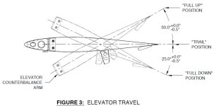
Also, at this point, the plans no longer have you verify the range of motion of the elevators, deferring to page 36-15, rev 1, where it refers to the since removed 11-02, figure 3 (image attached, from rev 0 of page 11-02). This implies that I should wait before I spend much time tweaking the elevator leading edges (I have some rubbing on the hinge brackets around 27° "up" deflection). Is waiting until I find out what's *really* needed the best plan?
 

Attachments

  • Screenshot 2024-06-24 150120.jpg
    Screenshot 2024-06-24 150120.jpg
    62.2 KB · Views: 12
Don, am I understanding you correctly that you are concerned about a 1/16" difference between the front to back gap between the counterbalance arm and HS? That's not much. A more important goal, IMO, is that both elevators swing freely through their entire range of motion. To me that suggests that all the elevator rod end attach bolts should be adjusted to the same length.

Also, I'd be concerned about not having any threads showing through the nutplate after your adjustment. (The plans have precise guidance on this that I can't recall right now) On my installation, in order to get everything lined properly with enough threads through the nutplate to ensure good locking, To make this happen I had to order the longer bolts (this was after talking to Vans Tech Support).

I went ahead and adjusted my elevator travel at the very end of Section 11 since there was a diagram showing travel limits.

You may have something else going on here and others may have more insight, but this is my 2 cents.
 
I went around in circles on my rod ends. The most important thing is that they are all in line - I used a bit of sting and a “pen end cone” to make sure.

This was my entry about it:
 
Don, am I understanding you correctly that you are concerned about a 1/16" difference between the front to back gap between the counterbalance arm and HS? That's not much. A more important goal, IMO, is that both elevators swing freely through their entire range of motion. To me that suggests that all the elevator rod end attach bolts should be adjusted to the same length.

I guess I may be over-thinking this, and suffering from a bit of analysis-paralysis when it comes to finalizing my rod end bearing adjustments. Given these constraints:
  • at least 1 thread showing past the end of a given nutplate (good to go, there, according to my pic), and
  • maintaining at least 1 5/8" separation between the torque tubes and rear spars (when elevator is in "trail" position?), and
  • no binding at the bearing throughout the full range of elevator motion,
it seems I can control the following parameters through bearing height adjustments (in no particular order):
  1. bearing height as close as possible to the recommended 13/16" height.
  2. consistent front-to-back gap between counterbalance arm and HS (1/8" called out in plans).
  3. distance from the elevator leading edge to HS rear spar web/hinge brackets.
  4. consistent rod end bearing heights on a given elevator.
  5. alignment of elevator trailing edge relative to HS rear spar/leading edge.
  6. torque tube/HS rear spar distance.
  7. consistency between left and right elevator adjustments.
Since adjusting for one parameter can affect the others, what's the priority order? I'm thinking 2, followed by 3, and then 1. I don't think 4, 5, 6, or 7 really matter in the grand scheme of things, provided the constraints are satisfied. Have I got this right? Of course, I'd prefer that everything be perfect, and fall into place exactly according to the plans, but it doesn't look like that's going to happen. ;)

I went ahead and adjusted my elevator travel at the very end of Section 11 since there was a diagram showing travel limits.

Curiously, the current rev of the plans (11-02, rev 1) no longer say anything about the travel limits. :unsure:

I went around in circles on my rod ends. The most important thing is that they are all in line - I used a bit of sting and a “pen end cone” to make sure.

I used your "pen-tip" trick ( :)(y) ) to verify hinge bracket/flange bearing alignment:

PXL_20240625_173450264.jpgPXL_20240625_173457390.jpgPXL_20240625_173508284.jpgPXL_20240625_173514781.jpgPXL_20240625_173522321.jpg
 
Last edited:
Back
Top