

Van's Air Force

The definitive Van's Aircraft support community! Buying, building or flying an RV? Join our exclusive family of mentors and enthusiasts!

Horizontal Stab Mounting Help

Clayvt

Well Known Member
Patron
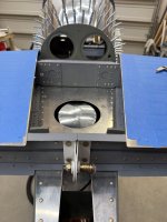
I am fitting up the horizontal stab for drilling but seem to have an issue.
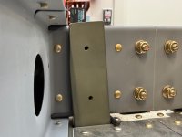
Just eyeballing before even measuring, when I clamp the rear spar to the vertical bars the leading edge is nowhere near centered. To get it centered while still making contact with the vertical bars it has to shift left so much that it runs into the horizontal stab skin and still needs to go more.

If I pivot the leading edge to get them roughly centered, then I have a gap on the left vertical bar about 3/16”.

Any guidance or help would be appreciated. IMG_8709.jpegIMG_8710.jpeg
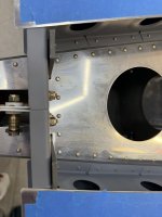
And yes, I will be going back and re squeezing all the rivets on the stab.
There are a few I am going to replace as I just don’t like the look of them. Can really tell I was at the beginning of the learning process with this!
 
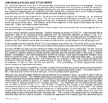
Suggest you go back and RE-READ the rigging instructions in the manual. The RV-6 required to square and align the H.S. with the airplane. On the RV-6, shims may be necessary between surfaces so that stress is not introduced into the airframe when bolts are torqued. Image attached is from the RV-6 manual.
 

Attachments

  • Screenshot 2026-07-02 at 3.24.25 PM.png
    Screenshot 2026-07-02 at 3.24.25 PM.png
    989.2 KB · Views: 16
It looks to me from your pics that your HS is not sitting in its final location exactly correct. If the centerline on your forward spar web on the HS is correct, it looks to be slightly right of the Cl on the aft fuselage bulkhead. Also looks like it might be slightly too far forward based on the observation that the vertical bars attaching the HS aft spar look like they might be bending slightly forward. The two spars on the HS do not sit flush on that aft deck. My forward spar is 1/8” above the aft deck. The aft spar a bit more. Keep in mind, two critical measurements are an equal distance from the HS tip to a common perfectly center location on the fuselage (or wingtip if was installed), AND a correct angle of incidence. Those two precise locations will make what you’re seeing look different.
Easiest first adjustment though is to move the HS slightly to the left.
 
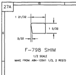
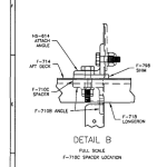
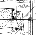
Don't forget about the F-798 shims and the rear spar sitting 3/16" off the deck before you drill.

May not fully solve your problems... but they are important to include. Check drawing 27A for the details.
 
Suggest you go back and RE-READ the rigging instructions in the manual. The RV-6 required to square and align the H.S. with the airplane. On the RV-6, shims may be necessary between surfaces so that stress is not introduced into the airframe when bolts are torqued. Image attached is from the RV-6 manual.
there is no mention of shimming (other than the 1/8” shims under the front spar in the 7 manual.
 
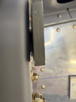
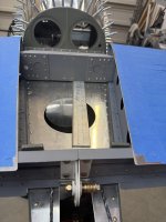
To get it square and on centerline it had to shift left so much that the right vertical bar interferes/overlaps the flange of the inboard rib of the stab.
And there is still a gap on the right vertical bar.
IMG_8715.jpegIMG_8714.jpegIMG_8713.jpeg


Where it is sitting right now, it has that 1/8" spacer up front (just temp, to mock it up not the final two spacers under each side) and the 3/16" in the rear. The stab is squared/equidistant to the firewall on each side.
This is how its sitting with the interference and gap.

The plans have you locating and drilling the holes without the spacers in place and putting them in after to match drill.
 
Last edited:
there is no mention of shimming (other than the 1/8” shims under the front spar in the 7 manual.
Not sure if it's in the manual or the plans, but there are two 1/8" shims under the forward spar and a 3/16 temporary spacer under the aft spar. That's for starters. Then the incidence is measured and shim(a) may need to be added forward to get the tooling holes level to the longerons. Then measurements from a central fuse reference to each tip to get sweep equal. Then, if that's not enough, the forward hole has almost zero room for error through the longeron. It's well documented here. Measure a thousand times before drilling then drill those two hole small and measure edge distance again. Better safe than...

Personally, the VS and Rudder were more time consuming.
 
Not sure if it's in the manual or the plans, but there are two 1/8" shims under the forward spar and a 3/16 temporary spacer under the aft spar. That's for starters. Then the incidence is measured and shim(a) may need to be added forward to get the tooling holes level to the longerons. Then measurements from a central fuse reference to each tip to get sweep equal. Then, if that's not enough, the forward hole has almost zero room for error through the longeron. It's well documented here. Measure a thousand times before drilling then drill those two hole small and measure edge distance again. Better safe than...

Personally, the VS and Rudder were more time consuming.
Larry is referencing DWG 27A.

Screenshot 2026-07-02 at 7.14.36 PM.pngScreenshot 2026-07-02 at 7.14.47 PM.pngScreenshot 2026-07-02 at 7.15.07 PM.png
 
Mine wasnt too dissimilar on first fit up.

IMG_0130.jpeg

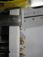
Ended up shimming with what appears to be 063 or so.

IMG_5216.jpeg

Almost 20y to the day…
 
Thank you. Ill put a call in to vans too but I was mainly wondering if it was ok to have that gap and fill it.
So long as the stab is centered and square.
No worries.
It’s been a long time but I have a feeling that they said that small a gap was fine to bend the 711Cs. Or to shim.
I’d be curious to see what they say.
 
So Vans says a shim is ok.
They also said I could square up the front then let the bolts on the rear draw bars to the spar. I don’t like the sound of that. I don’t want to have them under tension.

But now I have a new issue!
Again, just mocking up to see how everything will work out.
With the 1/8th shims up front the book says to put 3/16 under the rear spar to set the incidence and to verify by comparing the tooling holes on the inboard ribs to ensure it’s level to the deck.
My tooling holes are nowhere near close.
The front tooling hole looks on centerline but the rear is off center.

Anyone think using the skin would work?

Unless I use the nose rib hole?
I thought I read someone’s build log where they were told to not use the nose rib.

The plans aren’t exactly clear on this.
IMG_8737.jpegIMG_8736.jpeg
 
I recall measuring the tooling holes and found one, maybe two not centered. I ended up using measurements to get the incidence correct. It took forever first to figure out why then get it right. Plane flies straight so I guess I got it right.
 
Back
Top