What's new
Van's Air Force

Don't miss anything! Register now for full access to the definitive RV support community.

Help with Odd Vibration Needed

eastonale

Active Member
Patron
Hi Everyone,

On my 3 yr old RV-10 I've been struggling to find the cause of a really weird vibration that comes on with higher power settings. It makes the control stick vibrate and I can feel it in the bottom of the seat and on the floor. After balancing the prop, changing engine mounts, and doing just about everything else I could think of, the folks over at Van's let me come over and do a full spectrum analysis. During the run up we found typical vibration orders for a 6 cylinder with a 3 bladed prop, but we also found that as the RPM was advanced past about 2000 (about when the mp starts going up) an off the chart 2.5 order vibration showed up. I wasn't crazy after all!

So the question is, what could be causing this and what steps could I follow to troubleshoot? From my research online and after speaking with a few people, it seems that I may have some sort of torsional vibration that's being cause by cylinder imbalances which, according to one expert, is most likely induction based. It's not just one cylinder, or it would show up as a .3 order vibration (I believe). The prop is balanced to .05 ips by the way. I've inspected the intake system to include checking for leaks, checking intake valve lift and intake dry tappet valve clearance, and inspecting the hydraulic lifters. All seem normal. I'm running EFII electronic injection and I've flown with the injectors electronically balanced to all peak at within .3 gph and also let them run uncorrected, which is a "gami spread" of about 1.0 gph. It didn't seem to make any difference.

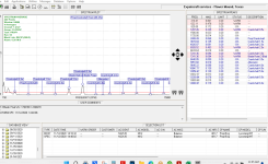
Any ideas? I've found a bunch of vibration discussions within this forum over the years but I've never found one with a 2.5 order. I'm attaching the analysis we did at 2300 RPM.

Engine Specs:

Barrett Precision Engines IO-540 narrow deck with cold air induction: 300 hours since rebuild
9-1 cylinders, Fly EFII System 32 ignition and injection
Whirlwind HRT 374 3-blade prop

Thanks!
 

Attachments

  • DynaVibe Vibration Analyzer 1st run 2300rpm.pdf
    112.1 KB · Views: 35
The prop should be indexed to the crankshaft. See link below.
For some users reclocking the prop 180 degrees have solved their problem.
Be sure to check with an A/I before proceeding.


Have you tryed to set spark advance to fixed 20 deg BTDC ?

Good luck
It’s a 3 blade but, from what I can gather, reclocking seems to be a 2 blade trick for the most part. But yes, I have reclocked 180.

I tried setting a flat 23 degree advance but would like to try that again while hooked up to the DynaVibe.
 
According to Barrett, nothing runs at that speed.
We had another Barrett CAI engine here in Australia that drove us nuts trying to find the vibration, it ended up being 7 of the pushrods were over spec slightly holding open valves. It got worse when the engine warmed up.

I would have to get the full story from the owner, but once the pushrods were replaced, the vibration was gone and the customer finally had a smile on his face.
 
New vibration or since new?
What did Barrett say when you called them?

What is a "full spectrum analysis"?
 
DO NOT LAUGH WHEN YOU READ THIS.......And seriously do not dismiss this.

I would pull all the pushrods and check them for length.

This story sounds identical to a client down here. Eventually it was found quite a few pushrods were too long. And this was a Barrett engine also. They didn't seem too interested in it when they were told.

Wasn't impressed. Nor was my mate.

PS I see Ashley has also commented. Both of us are not joking.
 
We had another Barrett CAI engine here in Australia that drove us nuts trying to find the vibration, it ended up being 7 of the pushrods were over spec slightly holding open valves. It got worse when the engine warmed up.

I would have to get the full story from the owner, but once the pushrods were replaced, the vibration was gone and the customer finally had a smile on his face.
DO NOT LAUGH WHEN YOU READ THIS.......And seriously do not dismiss this.

I would pull all the pushrods and check them for length.

This story sounds identical to a client down here. Eventually it was found quite a few pushrods were too long. And this was a Barrett engine also. They didn't seem too interested in it when they were told.

Wasn't impressed. Nor was my mate.

PS I see Ashley has also commented. Both of us are not joking.
How could it pass a compression test if the pushrods were holding valves open?
 
Push rods are selected based in their lengths. Lycoming makes 5 or 6 sizes of them. When you set the rocker arm clearances between .026-.080, you choose the length that gets you those clearances. That is done at a time when the lifters are unloaded (hydraulically). Usually only one size will get your clearances but going to the next one in either direction will get you to be over the limits. Not always but the pushrod selection for that rocker arm is a fairly easy process. You take a 3,4,5 or 6 lengths and install them and check the gap. I try to get ones to me in the middle of the gap range. After that is all done, you are set to load up the lifters with oil when you start the engine.
So I am wondering how they can be long if the gap was set correctly on overhaul. Do you have any records that tell you what that was from Barrett?
 
1/2 order vibrations are caused by gas pressure issues, most definitely looks like bad cylinder or cylinders not working like they should.

Below pasted from Dynamic Solution Systems manual:

Each combustion pulse acts much like a hammer blow, hitting the engine block with a pulse of energy. The vibration spectrum of such a pulse is a series of vibration spectral lines. These spectral lines will be at integer multiples of the firing rate of each piston. In a four stroke engine the piston fires every other revolution, therefore the fundamental spectral line will be at 1/2 the engine RPM, often called the 1/2 order vibration. The result will be a vibration signature that has spectral lines at the 1/2 order, 1P, 1-1/2P, 2P, 2-1/2P, 3P ... etc. In our experience, we have found that most 4 and 6 cylinder horizontally opposed IC engine produce these spectral lines in varying patterns but the levels are usually in the range of .2-.5 IN/S. . These readings are taken on the ground at typically 2500 RPM.
 
Push rods are selected based in their lengths. Lycoming makes 5 or 6 sizes of them. When you set the rocker arm clearances between .026-.080, you choose the length that gets you those clearances. That is done at a time when the lifters are unloaded (hydraulically). Usually only one size will get your clearances but going to the next one in either direction will get you to be over the limits. Not always but the pushrod selection for that rocker arm is a fairly easy process. You take a 3,4,5 or 6 lengths and install them and check the gap. I try to get ones to me in the middle of the gap range. After that is all done, you are set to load up the lifters with oil when you start the engine.
So I am wondering how they can be long if the gap was set correctly on overhaul. Do you have any records that tell you what that was from Barrett?
Thanks for the ideas everyone. I've already checked the dry tappet valve clearance of the intake valves and they all check out at .026-.080". Checking the exhaust valves are on the to do list. My symptoms would lean toward valves not opening all the way (pushrods too short) as opposed to them not closing (pushrods too long). Compression checks are perfect.

After cleaning all the injectors last week I went up and determined the uncorrected "gami spread" is about 1 gph and after electronically tuning the injectors I've got it down to where egt's all peak within .4 gph. Cylinders 2,3,5 were the outliers in that they were running lean so I added 5% fuel to them to achieve the .4. I obviously have a hp imbalance as a result but I'm not sure that a 5% difference is that out of the ordinary. Especially when running rich of peak during high power settings. The vibration appears to persist no mater whether I've got the injectors running with zero correction or with the 5% add on 2,3,5, though I'm going to try to see if it makes a difference on the Dynavibe readout.

As for the spark, I've done a lean of peak ignition check in flight as advised by the Savvy folks and see no indication that any plug is not acting the way it should. I plan on testing for the vibration on the Dynavibe with a flat ignition advance as compared to letting the variable timing do its thing.
 
For reference, here's a vib plot from an RV10/540 I did a while back, this is a 2 blade prop but pretty much what to expect with 1/2 orders:
(ignore the warnings, forgot to turn them off from the prop balance run)
Notice the difference in the crankshaft .5 order vs yours, this one is .075 vs yours around .25 IPS.
This .5 crankshaft order are low freq and generally what you will feel in your feet and the airframe.
The 2 are likely related, but what you're feeling is the .5 crankshaft vib.
The 3x vib is also quite high which may indicate a prop problem.

Troy%20Branch%20RV12%20vib%20survey-XL.png


The Below is a 3 blade MT on a 540...

Screenshot 2024-08-29 110607.png
 
Last edited:
Another trick is to put the accelerometer in the cockpit with you and use DynaVibe's Spectrum mode to look at the vibration in real time; put it on the stick and seat frame. The 2.5per is combustion related and can be caused by high compression and advanced timing, but you may be feeling the 1/2 per at 0.25 IPS. The 2.5 per is at the equivalent of 6000 RPM (would feel like a rotax 2-stroke buzzing). The engine dampers should take out the 2.5 per and leave you feeling the 1/2 per vibration. If it is the 1/2 per you are feeling then you can target cylinder issues such as spalled lifters, flat spot on cam, cracked plugs, leaking lifter, bent rod, etc.
Matt
Cool, trick. Anything that helps me narrow down the issue is what I'd really love to hear.

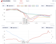
One slightly weird thing I've noticed when going over my engine data on Savvy is that when power is brought back to idle, especially during the flare, the EGT's go from a relatively tight grouping to some dropping excessively. Or, maybe it's #5 & 6 that aren't dropping as they should. Anyone know if this could be a clue? I know induction leaks would cause them to rise so this one puzzles me.

Screenshot 2024-08-29 at 11.55.31 AM.png
 
Hi Everyone,

On my 3 yr old RV-10 I've been struggling to find the cause of a really weird vibration that comes on with higher power settings. It makes the control stick vibrate and I can feel it in the bottom of the seat and on the floor. After balancing the prop, changing engine mounts, and doing just about everything else I could think of, the folks over at Van's let me come over and do a full spectrum analysis. During the run up we found typical vibration orders for a 6 cylinder with a 3 bladed prop, but we also found that as the RPM was advanced past about 2000 (about when the mp starts going up) an off the chart 2.5 order vibration showed up. I wasn't crazy after all!

So the question is, what could be causing this and what steps could I follow to troubleshoot? From my research online and after speaking with a few people, it seems that I may have some sort of torsional vibration that's being cause by cylinder imbalances which, according to one expert, is most likely induction based. It's not just one cylinder, or it would show up as a .3 order vibration (I believe). The prop is balanced to .05 ips by the way. I've inspected the intake system to include checking for leaks, checking intake valve lift and intake dry tappet valve clearance, and inspecting the hydraulic lifters. All seem normal. I'm running EFII electronic injection and I've flown with the injectors electronically balanced to all peak at within .3 gph and also let them run uncorrected, which is a "gami spread" of about 1.0 gph. It didn't seem to make any difference.

Any ideas? I've found a bunch of vibration discussions within this forum over the years but I've never found one with a 2.5 order. I'm attaching the analysis we did at 2300 RPM.

Engine Specs:

Barrett Precision Engines IO-540 narrow deck with cold air induction: 300 hours since rebuild
9-1 cylinders, Fly EFII System 32 ignition and injection
Whirlwind HRT 374 3-blade prop

Thanks!
Hi Mark,

Is the vibration on the control stick similar to the one in the attached video link?


Regards,
Jason
 
Does your engine mimic the indications of a stuck valve? If so this may be from some crud in the spider. This is mostly noticed as low fuel settings as the spideer ports are mostly closed (so crud has more of an effect).

Carl
 
For grins & giggles make a mark on the nose wheel tire sidewall with a white/silver Sharpie(tm) pen. Set up a GoPro, Virb, whatever - and video the nose wheel during flight.
 
Does your engine mimic the indications of a stuck valve? If so this may be from some crud in the spider. This is mostly noticed as low fuel settings as the spideer ports are mostly closed (so crud has more of an effect).

Carl
No spider installed as the electronic injection pulls off of a pressurized fuel rail. I’ve never had any “morning sickness” valve indications and my recent borescope show the valves looking normal. Of course a sticking intake valve would cause an imbalance but would be hard to diagnose I would think.
 
For grins & giggles make a mark on the nose wheel tire sidewall with a white/silver Sharpie(tm) pen. Set up a GoPro, Virb, whatever - and video the nose wheel during flight.
I did this a long time ago before I found it was a 1/2 order. Even flew without the fairings. The nose wheel rotates but not nearly fast enough to cause this type of buzz.
 
Push rods are selected based in their lengths. Lycoming makes 5 or 6 sizes of them. When you set the rocker arm clearances between .026-.080, you choose the length that gets you those clearances. That is done at a time when the lifters are unloaded (hydraulically). Usually only one size will get your clearances but going to the next one in either direction will get you to be over the limits. Not always but the pushrod selection for that rocker arm is a fairly easy process. You take a 3,4,5 or 6 lengths and install them and check the gap. I try to get ones to me in the middle of the gap range. After that is all done, you are set to load up the lifters with oil when you start the engine.
So I am wondering how they can be long if the gap was set correctly on overhaul. Do you have any records that tell you what that was from Barrett?

The engine supplier was not interested.

But they were all screwed up. And when the engine heated up enough in flight by say top of climb, tings were better. The alloy head moves away just enough to accomodate the over length rods. Amazing but true.

Of course there could be prop harmonics that others have covered but when you are all out of ideas......
 
I had issues with vibration at specific RPMs as well, 1800-1900. My new procedure is to take Dynavibe measurements at idle, 1500, 1800, 2000, max static (2350ish) at every clocking position (yes, all 6). What I found was when IPS was plotted against RPM for each clocking, there was one clocking where the line was flat. That clocking was where I did my final balance and it brough the line down at all RPM. Still higher than I would like at 1800-1900 RPM, which is around my downwind RPM, but was acceptable.

Just a thought.
db
Interesting. I’m curious if you had a two or three blade prop?
 
Back
Top