
Van's Air Force
You are using an out of date browser. It may not display this or other websites correctly.
You should upgrade or use an alternative browser.
You should upgrade or use an alternative browser.
Help comm or vor
- Thread starter Mycool
- Start date

Mycool
Well Known Member
Reply
If it were only that easy to get a visual on what the coax is connected to. What I need is someone with know how to help me maybe run a test on wire to to help figure out without having to cut open tail. I will connect a handheld with vor feature to check. Thought there would be an easier way.
If it were only that easy to get a visual on what the coax is connected to. What I need is someone with know how to help me maybe run a test on wire to to help figure out without having to cut open tail. I will connect a handheld with vor feature to check. Thought there would be an easier way.
I will connect a handheld with vor feature to check.
That’s unlikely to help. If there’s a strong VOR nearby, your handheld will hear the signal, even if connected to a com antenna.
If there are no com antennas on the tailcone, you might guess that it’s connected to a nav antenna. But it’s a guess. Could be an old marker beacon antenna, or a stand-alone glide slope antenna, or a transponder antenna. If you want to know for sure, by far the easiest route is to remove the aft bulkhead (get an electric screwdriver) and follow the coax to see what it’s attached to.
wirejock
Well Known Member
Toner
If there's access to the panel end of the coax, use a telecom toner and inductive pickup. Clip the toner to the center and outer sleeve. Go back and wave the inductive amp. You'll hear a very distinctive warbling tone. You'll have to try each coax to find it.
I was in Telecom for 20+ so I still have all my tools. Inductive amp is so sensitive we used to hold it by the ear and slide fingers over the wires or termination blocks to narrow the search then start poking around. Only caveat is the 110v ring voltage really stings.
GalinHdz
Well Known Member
Sorry to tell you but there is no way around it. Both Comm and VOR are in the same RF band (VHF 108-137Mhz) so the only way to know is to follow the coax and see which antenna it is actually connected to....follow the coax to see what it’s attached to.

Transponders are at a completely different RF band (UHF 1030-1090MHz) so the antenna will be very different.
Last edited:
Mike S
Senior Curmudgeon
https://www.harborfreight.com/cable...MIpPaOyLri_gIV7BCtBh1SwgcoEAQYASABEgJpwfD_BwE
A signal tracer might do the job.
A signal tracer might do the job.
Mark33
Well Known Member
…..(snip)…If it were only that easy to get a visual on what the coax is connected to.
Perhaps you could post a photo of the antennas mounted in the area of the tail section.
Can you not get to the antennas at all?….I’m having a hard time being able to visualize your situation. If you can at least get to each end of the coax I’d think a simple ohm meter would answer your question.
David Paule
Well Known Member
Can you see what box the cable starts from?
Dave
Dave
rzbill
Well Known Member
Can you not get to the antennas at all?….I’m having a hard time being able to visualize your situation. If you can at least get to each end of the coax I’d think a simple ohm meter would answer your question.
Antennae on glass birds are commonly buried in the structure so the only visible evidence is the coax connection, wherever the builder decided to put it. Even with that, the detail design of the antenna would be unknown to anyone but the builder.
Mark33
Well Known Member
Antennae on glass birds are commonly buried in the structure so the only visible evidence is the coax connection, wherever the builder decided to put it. Even with that, the detail design of the antenna would be unknown to anyone but the builder.
Roger that….I didn’t realize it was a glass bird.
gmcjetpilot
Well Known Member
Coaxial type is not an indication of COM, ELT [/B, VOR all GPS can use RG58 (which is old school most have gone to RG400).
As said what antenna is back there
If you see nothing then it could have been removed or builder put some hidden antenna in the intersection fairing (typical of Elt antennas) or in Vert or Hroz Stab fairings.
Get antenna analyze and see what it's FREQ response, impedance if any (open or short).
It really is not Brain Engineering or Rocket Surgery. What other antennas are in the plane and what avionics are there. If there is NO VOR receiver there is a sign. If there is an ELT and you don't SEE an ELT, where there is a clue. Same with COM. I have seen older planes with wiring "Retired In Place", usually factory planes, but kit planes WHO KNOWS? The quality of kit planes is fairly high especially with Van's RV kits. However I have seen wackadoodle stuff.
Last edited:
Mycool
Well Known Member
Can you see what box the cable starts from?
Dave
No as it's in the Qb build stage and yes it's a glass airplane.
Mycool
Well Known Member
Coaxial type is not an indication of COM, ELT or VOR use RG58 (which is old school most have gone to RG400).
As said what antenna is back there
If you see nothing then it could have been removed or builder put some hidden antenna in the intersection fairing (typical of Elt antennas) or in Vert or Hroz Stab fairings.
Get antenna analyzer and see what it's FREQ response, impedance if any (open or short).
It really is not Brain Engineering or Rocket Surgery. What other antennas are in the plane and what avionics.
None, if I were able to see the physical antenna it would be easy.
Mike S
Senior Curmudgeon
Hi Larry, just to be clear, the warbling will be comm or VOR?
If you are asking about the unit I linked to----you would clip the tone generator to the antenna, and use the probe to test each coax to find the signal. That is, assuming the signal will couple from the antenna to the coax.
I have not tried to trace anything like this, but I can tell you it works great for finding individual runs of CAT 6 in a bundle.
I think it will work in your situation, but not sure.
wirejock
Well Known Member
Signal tracer
The signal tracer Mike posted does two things. In "tone" mode it puts a warbling sound on the positive clip. Whatever it's connected to will have the tone. I've never tried sending tone over an antenna. In theory it should work. It's connected to the center wire on the coax. You need the black clip connected to ground somehow. Some antennas have a coil that may impede the tone.
You should be able to probe around with the inductive amp under the panel and narrow the sound to the device. You have to disconnect at the radio end to really zero in on the loudest connection.
When you probe the opposite end of the wire, it will be really noticeable loud warbling tone.
The continuity function will light if the two leads are shorted. It's used to verify a wire has continuity from one end to the other. We usually shorted two wires in the cable and clipped to the same pair on the other end. If it lights, the circuitnis good. It will also light if there's 48V telephone power on the pair.
If you are asking about the unit I linked to----you would clip the tone generator to the antenna, and use the probe to test each coax to find the signal. That is, assuming the signal will couple from the antenna to the coax.
I have not tried to trace anything like this, but I can tell you it works great for finding individual runs of CAT 6 in a bundle.
I think it will work in your situation, but not sure.
The signal tracer Mike posted does two things. In "tone" mode it puts a warbling sound on the positive clip. Whatever it's connected to will have the tone. I've never tried sending tone over an antenna. In theory it should work. It's connected to the center wire on the coax. You need the black clip connected to ground somehow. Some antennas have a coil that may impede the tone.
You should be able to probe around with the inductive amp under the panel and narrow the sound to the device. You have to disconnect at the radio end to really zero in on the loudest connection.
When you probe the opposite end of the wire, it will be really noticeable loud warbling tone.
The continuity function will light if the two leads are shorted. It's used to verify a wire has continuity from one end to the other. We usually shorted two wires in the cable and clipped to the same pair on the other end. If it lights, the circuitnis good. It will also light if there's 48V telephone power on the pair.
GalinHdz
Well Known Member
Good luck on the tone generator but it more than likely will not work for identifying the antenna. Neither will an ohm meter. Both Comm & VOR antennas are cut to the same band so they will seem identical to both detection methods. RF behaves very different from Audio and Telephone signals.
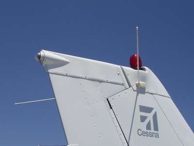
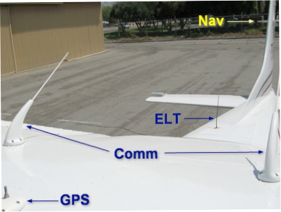
If the fiberglass isn't too thick you can try shining a very bright light on one side of the vertical stabilizer. A bright LED is best since it does not generate much heat. Maybe you can see what kind of shadow the antenna makes which will help in determining the type. Antennas designed for fiberglass applications need a built in ground plane so they tend to have a distinct shape and a specific installation method. These are two common Comm antennas for fiberglass application. You can see their distinct shape.


Also, Comm antennas "should" be installed vertically while VOR antennas "should" be installed horizontally. If it is in the vertical stabilizer, then it more than likely is a Comm antenna. But then again the coax might not be connected to anything.
If the fiberglass isn't too thick you can try shining a very bright light on one side of the vertical stabilizer. A bright LED is best since it does not generate much heat. Maybe you can see what kind of shadow the antenna makes which will help in determining the type. Antennas designed for fiberglass applications need a built in ground plane so they tend to have a distinct shape and a specific installation method. These are two common Comm antennas for fiberglass application. You can see their distinct shape.
Also, Comm antennas "should" be installed vertically while VOR antennas "should" be installed horizontally. If it is in the vertical stabilizer, then it more than likely is a Comm antenna. But then again the coax might not be connected to anything.
Last edited:
invisible antenna
OK, glass airplane.
The antenna type is of an unknown type and may be just a couple of strips of copper foil buried in the glass. Right?
Two approaches:
1. Use the telephone buzz box or similar method mentioned near the begining of this thread to locate the antenna. If it ends up in the H. stab - it is a nav/vor antenna. If it is in the vert stab, it is intended to be the comm/vhf antenna. But you still don't know if the prev builder got it right and there is a usable antenna at the end of the cable.
2. Or, find someone with a 50 dollar vector analyzer and scan for low VSWR from , say, 100mhz to 150 mhz. The dip should favor either the nav or comm range. It is 90 percent likely that it is one or the other. This will also tell you if the antenna is any good. Cable attenuation will make the antenna look a little better than it really is, but you should see a range of frequencies below 3 to 1.
Good luck
Ron
I'm curious...wires have two ends. Is it not possible to trace the cable to whatever box it's connected on the avionics end?

