I'm planning a Skyview installation, and I need to make lots of y-junctions. Has anyone ever taken apart the Dynon SV-NET-SPL to see how the connections are made in there? I'm wondering if they have managed to get two 22 gauge wires into a single d-sub pin, or if there is some soldering in there or what.

Van's Air Force
You are using an out of date browser. It may not display this or other websites correctly.
You should upgrade or use an alternative browser.
You should upgrade or use an alternative browser.
Has anyone seen the inside of the Dynon Network Splitter?
- Thread starter jaredyates
- Start date

I have one of those network splitters, and yes they just stuff the 2 wires into the pin and crimp it. They probably have D-sub pins with a slightly larger hole. I tried to stuff two 22 gauge wires into the gold plated mil-spec D-sub pins and it was a really tight fit. Almost impossible without some tenacity to try and get all of the wire strands into the pin.
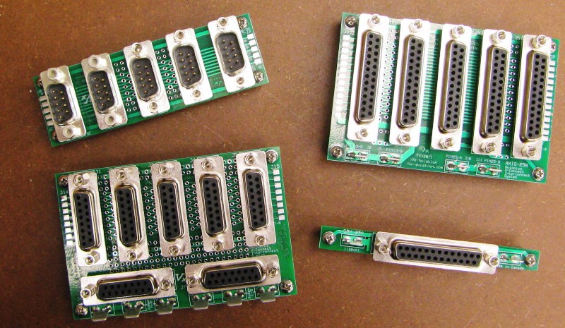
I ended up using lots of these "hubs".
Dynon now sells something similar call the SV-NET-HUB.
I ended up using lots of these "hubs".
Dynon now sells something similar call the SV-NET-HUB.
Last edited:
Thanks Bruce, is that the one from Vern?
N941WR
Legacy Member
When I installed my SkyView some years back, I bought two of their five port hubs.
One is mounted in the back, similar to what Bruce, but on the rib that supports the pitch servo. Both of my ADAHRS units, the pitch servo, and the wires leading forward are plugged in there.
There is a second one on the subpanel that the wire from the aft hub is plugged into, along with the roll servo, and a few other things. Then there is a short cable run from that hub to the SkyView.
Very easy to install and well worth the money!
Yes, Vern's design. I used the schematic download from makerplane.org and had several boards fabbed up. Much cheaper than Dynon's version. I bought the D-sub connectors from digikey and with a few minutes of soldering had them built.Thanks Bruce, is that the one from Vern?
wirejock
Well Known Member
Schematic
Bruce
Would you consider sharing the file?
Makerplane has suspended download.
Yes, Vern's design. I used the schematic download from makerplane.org and had several boards fabbed up. Much cheaper than Dynon's version. I bought the D-sub connectors from digikey and with a few minutes of soldering had them built.
Bruce
Would you consider sharing the file?
Makerplane has suspended download.
If it isn't Vern's intent to share the file, then I wouldn't want to undermine that. But if he doesn't see it as an intellectual property issue and it's just a matter of logistics, I'd be interested in soldering up one too. I'm having a hard time understanding why they are so expensive while seemingly made from inexpensive parts. Am I underestimating the cost of the parts, or is this not like a $10 project?
These 9-pin boards are great for joining up the Skyview Network, but by my count I've still got a dozen other connections that need to be doubled for the two screens. These are mostly serial and audio. Someone suggested to Vern in the makerplane forum that he draw up a board that would handle the skyview network with a few slots and also have a second trio of electrically connected dsubs that were separate from the 9-pin network connectors. I'd envision a board with three 25-pin connectors with their pins paired (the three connectors would serve one screen in, second screen in, and paired out) and 5 9-pin connectors with their pins each joined like the current hubs. I'd love to see them all on the same board, and maybe with a bonus 25-pin grounding connector with all of the pins shorted to each other. Vern didn't seem to interested when he replied in that thread, but it seems like it would be really handy for a dual-screen Skyview installation. With so many people running dual Skyview setups, I'm wondering how everyone else gets these non-network cables joined up in an elegant way without something like this.
Maybe someone around here likes to draw up circuit boards? I don't know how to do it, and it probably wouldn't be worth learning just for this task.
az_gila
Well Known Member
If it isn't Vern's intent to share the file, then I wouldn't want to undermine that. But if he doesn't see it as an intellectual property issue and it's just a matter of logistics, I'd be interested in soldering up one too. I'm having a hard time understanding why they are so expensive while seemingly made from inexpensive parts. Am I underestimating the cost of the parts, or is this not like a $10 project?
.....
It sounds like a hacking issue, not an intellectual property issue.
.....
REMOVED BY VERN'S REQUEST
Last edited:
Since the 9 wires are connected in parallel via the D-Subs, could the wires just be spliced (soldered or crimped) without using a hub and D-Subs?
In my installation I'm considering Amp PIDG crimped-on splices as the most likely alternative to a hub. I suppose the hub might allow more flexibility down the road, but that may be a solution for a problem that will never materialize. Based on Bruceh's reply it sounds like reproducing Dynon's splitter technique inside of the 37-pin shell is not going to be the best option.
For the serial/audio connections, I don't see how the function of a hub is worth the expense of the hardware, especially if a hub is going to be $100 just for those connections. This is where I think there'd be real value in a combined hub as mentioned above. Crimped splices are much less expensive than the combined expense of the hub and dsub pins, and I'm willing to assume that they are comparable when it comes to reliability, assuming they are executed correctly.
As for the network cables, I'm currently only short one plug, so I could serve my needs by making up a single splitter. If I were to add anything in the future, such as autopilot servos or another ADAHRS, then the network hub would be nice to have. I can't see that there is a big advantage to adding it now vs later.
Last edited:
vlittle
Well Known Member
If it isn't Vern's intent to share the file, then I wouldn't want to undermine that. But if he doesn't see it as an intellectual property issue and it's just a matter of logistics, I'd be interested in soldering up one too. I'm having a hard time understanding why they are so expensive while seemingly made from inexpensive parts. Am I underestimating the cost of the parts, or is this not like a $10 project?
These 9-pin boards are great for joining up the Skyview Network, but by my count I've still got a dozen other connections that need to be doubled for the two screens. These are mostly serial and audio. Someone suggested to Vern in the makerplane forum that he draw up a board that would handle the skyview network with a few slots and also have a second trio of electrically connected dsubs that were separate from the 9-pin network connectors. I'd envision a board with three 25-pin connectors with their pins paired (the three connectors would serve one screen in, second screen in, and paired out) and 5 9-pin connectors with their pins each joined like the current hubs. I'd love to see them all on the same board, and maybe with a bonus 25-pin grounding connector with all of the pins shorted to each other. Vern didn't seem to interested when he replied in that thread, but it seems like it would be really handy for a dual-screen Skyview installation. With so many people running dual Skyview setups, I'm wondering how everyone else gets these non-network cables joined up in an elegant way without something like this.
Maybe someone around here likes to draw up circuit boards? I don't know how to do it, and it probably wouldn't be worth learning just for this task.
Or you could just ask Vern for the files.
Thanks Vern, did you ever draw a file that had something similar the 9-pin network connectors and the three 25-pin connectors on a common board? I was under the impression that such a thing had not yet been created.
vlittle
Well Known Member
Thanks Vern, did you ever draw a file that had something similar the 9-pin network connectors and the three 25-pin connectors on a common board? I was under the impression that such a thing had not yet been created.
I have many configurations of wiring busses that I have developed for other uses. The most complex is a combination of 25 pin and 9 pin busses, plus various 'mop up' circuits (mono and stero audio mixer, wig-wag controller, annunciator controller, 2-axis trim/autotrim controller, and some secret sauce).
Currently 'productized' wiring hubs:
AXIS-9A (copied by Dynon)
AXIS-15A (popular).
AXIS-25A (very popular).
AXIS-future (as described above- work in process).
Last edited:
Carl Froehlich
Well Known Member
I'm planning a Skyview installation, and I need to make lots of y-junctions. Has anyone ever taken apart the Dynon SV-NET-SPL to see how the connections are made in there? I'm wondering if they have managed to get two 22 gauge wires into a single d-sub pin, or if there is some soldering in there or what.
Just so we don't loose the the original question, it is simple to just solder wires together to make one cable into 2, 3 or more that have the needed D connector plug. There is nothing here that needs considerations such as impedance. Just make sure you match up the wires. I did heat shrink on each wire splice, then heat shrink over the entire joint. Note - the solder joints are done with wires all pointing the same direction. This provides excellent mechanical stability and, in my opinion, takes up less room and is a lot easier than the clunky D connector boards. I would never consider crimp splices for this application.
I did split up the joints such that each SkyView had about the same number of connected devices. I did run a single cable between the two open network connections in each displays to make sure there were no orphans. I added a spare network connector as I figured I'd be adding something else along the way - and I did.
Carl
I have many configurations of wiring busses that I have developed for other uses. The most complex is a combination of 25 pin and 9 pin busses, plus various 'mop up' circuits (mono and stero audio mixer, wig-wag controller, annunciator controller, trim controller, and some secret sauce).
I wonder if it could be worthwhile for you and also not super-expensive for me to hire you to design a board with 5 or so 9-pin spots all in parallel and 3 or so 25-pin spots all in parallel? I ask with the understanding that your time may be worth enough to drive the cost out of a practical range, but I figure the only way to find out is to ask.
Also, it may not be polite to ask, and you are welcome to say so if that is the case, but are the complete hubs so expensive because the parts are expensive? I ask in case the assembly labor is the main driving factor. I'm very comfortable with soldering and would get some fun out of putting one together.
Am I just being too much of a tight wad?
Thanks for bringing it back around Carl. When you say all the wires pointed in the same direction, do you mean all three wires, such that the three are coming in side by side and ending in a stump? I've drawn a picture with what I think you are saying on the top part of the image.Note - the solder joints are done with wires all pointing the same direction. This provides excellent mechanical stability and, in my opinion, takes up less room and is a lot easier than the clunky D connector boards.
Carl

I envisioned crimping them similar to as shown at the bottom of the image.
Carl Froehlich
Well Known Member
Thanks for bringing it back around Carl. When you say all the wires pointed in the same direction, do you mean all three wires, such that the three are coming in side by side and ending in a stump? I've drawn a picture with what I think you are saying on the top part of the image.
I envisioned crimping them similar to as shown at the bottom of the image.
Yep - that is what I mean.
I find this to be far easier as you can slip the heat shrink over the joint after solder, then a large heat shrink over all the now covered joint to finich. Use a tie wrap or such to hold all the wire together and then have the joint in your typical wire bundle. As with all such connections, the mechanical properties tend to be the most important.
As I mentioned earlier, solder - do not crimp.
Carl
vlittle
Well Known Member
I wonder if it could be worthwhile for you and also not super-expensive for me to hire you to design a board with 5 or so 9-pin spots all in parallel and 3 or so 25-pin spots all in parallel? I ask with the understanding that your time may be worth enough to drive the cost out of a practical range, but I figure the only way to find out is to ask.
Also, it may not be polite to ask, and you are welcome to say so if that is the case, but are the complete hubs so expensive because the parts are expensive? I ask in case the assembly labor is the main driving factor. I'm very comfortable with soldering and would get some fun out of putting one together.
Am I just being too much of a tight wad?
The existing AXIS-9A and AXIS-25A designs do exactly what you are looking for and occupy about the same space. I no longer manufacture them because it is not profitable.
rv7charlie
Well Known Member
To address the questions about soldered/crimped wire junctions instead of a circuit board that 'daisy chains' the pins for several connectors:
It is electrically equivalent (with reasonable length considerations) to crimp a single 'pig tail' wire into the dsub pin, and crimp or solder (your choice; makes no difference) multiple wires to the 'pig tail'. A system that accepts either 'star' or 'daisy chain' configuration would device-limited by how many loads/sources it can supply/sink.
PS: Before saying that soldering causes stress risers (with the implication that crimping does not), do your homework first.")
Charlie
It is electrically equivalent (with reasonable length considerations) to crimp a single 'pig tail' wire into the dsub pin, and crimp or solder (your choice; makes no difference) multiple wires to the 'pig tail'. A system that accepts either 'star' or 'daisy chain' configuration would device-limited by how many loads/sources it can supply/sink.
PS: Before saying that soldering causes stress risers (with the implication that crimping does not), do your homework first.
Charlie
az_gila
Well Known Member
Geez, Gil. This is a copyright violation... please remove this image. I am willing to provide the source code under terms of the TAPR open hardware license free of charge, but I don't want uncontrolled (copyright violating) documentation posted.
Folks can contact me by PM or email if they want the source package.
Removed as requested and with apologies, but note that the picture is on an open web site...
vlittle
Well Known Member
Removed as requested and with apologies, but note that the picture is on an open web site...
Thanks! MakerPlane has a license to use copyrighted materials from me.
Cheers, Vern
az_gila
Well Known Member
Thanks! MakerPlane has a license to use copyrighted materials from me.
Cheers, Vern
Vern, you have to go back and edit your post #13 yourself, I can't remove that picture...
vlittle
Well Known Member
Vern, you have to go back and edit your post #13 yourself, I can't remove that picture...
Got it, thanks.
V
bpattonsoa
Well Known Member
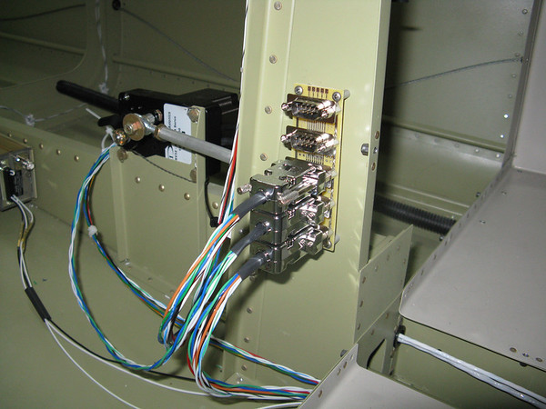
Not a splitter, but this is what I developed to run a full dual Skyview system and avoid most of the issues relating to wiring.
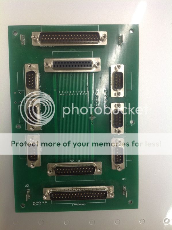
The board was developed by me on an online site that gives you a program and then you can order the results. I got 4 at about $40 each not including the solder in type Dsubs.
There are two 25 pin Dsubs on the board. One for each Skyview system. Twenty five of the wires on the display 37 wire cable go to the Dsub including all the power inputs (two for ground and power because the current capacity on a single Dsub pin is 5 amps). The board connects the things that need to be connected together with two displays like the 5 RX & TX, GPS inputs and power, transponder and ADSB stuff and some contact inputs. The power supplies are separate.
The six 9 pin Dsubs go to components or the airframe. They contain all the wires necessary for the component resulting in a dedicated cable to the: Transponder, ADSB Receiver, GPS, dimmer and audio circuits. One is the unused RX & TX and some contact inputs. One plug is the airframe inputs to the system: Power to each display, power to transponder and ADSB receiver, and inputs such as transponder ident switch.
On the corners of the board are 4 ground tabs that provide the system grounds and ground to the dedicated common point grounds that are the two 37 pin dsubs. There are also points where jumpers can be used to correct errors in the design (one in use) or make other direct soldered wire connections.
In and working in my -10. I also have a Dynon Network connector mounted just above the board. Makes for a mess of cables, but is a simple solution.
Dynon and Advance have these also, but you have to buy a complete panel from them, they don't sell them separately. Theirs also include a bunch of great things like trim control, power to aircraft lighting, and much more. They should sell them to the public.
....I no longer manufacture them because it is not profitable.
And there is the answer exactly as to why something with "x" (small) $$'s of parts costs "Y" (larger) $$'s to purchase. TIME also has a value; more for some, less for others.
Cheers,
Stein

