Any help or suggestions appreciated!
I've been working at the wiring of my 6 for a while now and even though I'm closer there continues to be one persistent problem that I' now turning to the forums for any suggestions for solving.
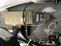
I have the GRT HXr EFIS with the Trig TY 91 radio and the GRT adapter between between the two. A fairly simple wiring job, two wires from the radio to the adapter, two wires from the adapter to the EFIS. Those two wires are the communication path between the radio and EFIS; and the radio can be controlled through the EFIS without a control head. These two wires have been checked many times, they are pinned correctly. The radio was sent off and tested, and sent back with confirmation that it's functional; power to the radio is confirmed, along with the correct grounding. The Adapter is functional and communicating with the EFIS, confirmed by GRT. Continuity has been checked on all wires while pinned in the Dsubs and there are no issues there.
I am at a loss at this point. I've been talking with GRT to find an answer or any suggestion of what to look for to solve the issue but no luck so far.
If anyone has any ideas, or come across this before, or has any info or suggestions of what to check, all are appreciated.
Den
I've been working at the wiring of my 6 for a while now and even though I'm closer there continues to be one persistent problem that I' now turning to the forums for any suggestions for solving.
I have the GRT HXr EFIS with the Trig TY 91 radio and the GRT adapter between between the two. A fairly simple wiring job, two wires from the radio to the adapter, two wires from the adapter to the EFIS. Those two wires are the communication path between the radio and EFIS; and the radio can be controlled through the EFIS without a control head. These two wires have been checked many times, they are pinned correctly. The radio was sent off and tested, and sent back with confirmation that it's functional; power to the radio is confirmed, along with the correct grounding. The Adapter is functional and communicating with the EFIS, confirmed by GRT. Continuity has been checked on all wires while pinned in the Dsubs and there are no issues there.
I am at a loss at this point. I've been talking with GRT to find an answer or any suggestion of what to look for to solve the issue but no luck so far.
If anyone has any ideas, or come across this before, or has any info or suggestions of what to check, all are appreciated.
Den