What's new
Van's Air Force

Don't miss anything! Register now for full access to the definitive RV support community.

GPS Antenna Installation?

claycookiemonster

Well Known Member
I'm mounting both a Dynon and a Garmin GPS antenna. I've looked through both installation manuals and there seems to be very little guidance. I thought there might be heading alignment or horizontal relative to flight attitude limitations, but I haven't found any. I'm going to do the small shelf below the cowling just off the firewall.

Is this really as simple as it appears? Put a shelf out there, drill mounting holes in it and run the wiring?
 
If the antenna is for a TSO 145/146 (“IFR”) unit then the Garmin manual definitely has antenna mounting directions wrt location. If this is for a vfr only unit, then I say do what you want, although personally, as an old electronics guy, I try hard to not put any solid state electronics in hot areas (do either antennas have active electronics?). Also, know that there have been some active antenna electronics failures where the failed unit radiated a signal and blanked out another nearby gps antenna.
 
I'm mounting both a Dynon and a Garmin GPS antenna. I've looked through both installation manuals and there seems to be very little guidance. I thought there might be heading alignment or horizontal relative to flight attitude limitations, but I haven't found any. I'm going to do the small shelf below the cowling just off the firewall.

Is this really as simple as it appears? Put a shelf out there, drill mounting holes in it and run the wiring?

You don't say what avionics you're feeding the GPS signal to, but for my 430W, section 2.4.1 GPS Antenna Location lists "guidelines", not requirements, and each one uses the word "should", not "shall".

Plenty of people, me included, have put one or more GPS antennae on a shelf mounted to the firewall, under the cowling, with no issues. Doubtless someone will come on here and tell you that it's illegal, or that they did it and almost died, etc.

It's EAB...give it a try and see how it works for you.

ETA: Oh, and don't forget the *MINIMUM* coax length that is called out...an antenna under the cowling will be so close to the avionics you'll need to coil up all that length under the panel and secure it (the minimum is to ensure the proper signal strength at the electronics). Read your entire installation manual *carefully*.
 
The Garmin antenna is feeding both a G5 as well as a GNC355. The Dynon antenna is feeding a Sky View HDX 1100.
I looked in the GPS antenna installation portion of both manuals and didn't find much specificity. I expected to find it. Nothing has been done yet, so nothing to undo, but please lead me to the details I apparently missed.
 
Coil length ?

ETA: Oh, and don't forget the *MINIMUM* coax length that is called out...an antenna under the cowling will be so close to the avionics you'll need to coil up all that length under the panel and secure it (the minimum is to ensure the proper signal strength at the electronics). Read your entire installation manual *carefully*.

Good input and not sure what equipment you are referencing but if a Garmin G5 or G3X mounted on the glare shield (They make a GPS antenna specifically for that application) how much antenna cable does one "coil'? Seems glare shield mounting would have even less distance than under the cowling. I've looked and cannot find the spec.
 
Good input and not sure what equipment you are referencing

The 430W, as I said in my post, since that's what I have.

but if a Garmin G5 or G3X mounted on the glare shield (They make a GPS antenna specifically for that application) how much antenna cable does one "coil'? Seems glare shield mounting would have even less distance than under the cowling. I've looked and cannot find the spec.

I can't help you with a G5 or a G3X. You'll have to find the info on your own, or contact Garmin or perhaps someone here can point you to the info. All I can say is that this info is the *GNS430* Installation Manual, Section 3.10.1:

Once the antenna mounting position has been prepared, route the coax cable from the antenna to the 400W Series unit. Proper selection of coax cable and assembly of connectors is critical to GPS signal performance. The cable loss from the GPS antenna shall be between 1.5 dB and 6.5 dB in order to maintain proper rejection to interference signals.
The coaxial connectors and adapters, such as TNC to BNC, add additional loss to the cable and should be considered when computing the cable loss. A typical loss of 0.2 dB can be used for each connection. To maintain integrity of the WAAS signal, the GPS antenna coaxial cable must have a minimum of two shields (e.g. RG-400 or RG-142B).
NOTE
If RG-142B or RG-400 is used, 1.5 dB equates to a length of approximately 6.5 feet of cable with a connector on each end. RG-142B or RG-400 cable can be used as long as the length is less than 35 feet. For longer lengths, use low-loss double or triple shielded 50Ω coax.
For very short runs, where the loss is less than 1.5 dB, additional cable should be used to increase the loss to within 1.5 dB to 6.5 dB. This additional cable may be coiled, taking into account the minimum bend radius of the cable.

But again, that's for a 430, NOT necessarily for your equipment. You *sure* there's no info like this in the Installation Manuals you have?
 
Last edited:
Good input and not sure what equipment you are referencing but if a Garmin G5 or G3X mounted on the glare shield (They make a GPS antenna specifically for that application) how much antenna cable does one "coil'? Seems glare shield mounting would have even less distance than under the cowling. I've looked and cannot find the spec.

OK, now I'm going to bag on you a bit. It took me less than 30 seconds of an on-line search to find the G5 manual, download it, and look in the section labelled "Antenna Cable Installation and Connections", and guess what I found:

4.2 Antenna Cable Installation and Connections
NOTE
GPS antenna cable loss must be between 1.5 dB and 6.5 dB in order to maintain proper
rejection of interference signals. If RG-142B or RG-400 is used it must be between 6.5
and 35 feet long to meet the cable loss requirement. For longer lengths, use low-loss
double or triple-shielded, 50 Ω coaxial cable.
Proper selection of coaxial cable and assembly of connectors is critical to GPS signal
performance. Use a TNC connector, AMP P/N 31-4452, to connect the coaxial cable to the
GPS antenna. Use a BNC connector, AMP P/N 225395-6, to connect the coaxial cable to the
G5.
Additional loss from coaxial connectors and adapters, such as TNC to BNC, should be
considered when computing cable loss. A typical loss of 0.2 dB can be used for each
connection.
For very short runs, where the loss is less than 1.5 dB, additional cable should be used to
increase the loss to within 1.5 dB and 6.5 dB. This additional cable may be coiled, taking into
account the minimum bend radius of the cable

So there it is, right there. Did you *download and read* the Installation Manual, as you should have?

Downloading and READING the G5X Installation Manual is left as an exercise for the reader.

Sigh.
 
The Garmin antenna is feeding both a G5 as well as a GNC355. The Dynon antenna is feeding a Sky View HDX 1100.
I looked in the GPS antenna installation portion of both manuals and didn't find much specificity. I expected to find it. Nothing has been done yet, so nothing to undo, but please lead me to the details I apparently missed.

And you, too. See post above about the section of the G5 manual.

Are you guys READING THE ENTIRE MANUAL before you go banging on installing stuff? 'Cause it sure doesn't seem that way to me.
 
Thanks

My point was glare shield mounting (which Garmin says is ok) is already shorter than my inside the cowling method which I've used successfully in my 3 experimentals built and flying. Thanks for checking in less than 30 secs, G3X install manual? (Which is my controlling document for my systems)
 
Last edited:
Did you find a gps antenna designed to feed two gps radios? You can’t just feed one output thru a conventional splitter.
 
My point was glare shield mounting (which Garmin says is ok) is already shorter than my inside the cowling method which I've used successfully in my 3 experimentals built and flying. Thanks for checking in less than 30 secs, G3X install manual? (Which is my controlling document for my systems)

What does glareshield vs. under-cowling mounting have to do with anything related to the minimum length of cable? As far as the *antenna* goes, there are myriad places it can be mounted, but ALL of them will require the minimum cable length to ensure to 1.5-6.5 dB signal loss.

Maybe check section 14.8 in the G3X manual.

FWIW, like you my under-cowling mount for both 430W and Dynon SV antennae (430W coax of required minimum length coiled under the dash) works perfectly fine.
 
I'll take 30 secs

What does glareshield vs. under-cowling mounting have to do with anything related to the minimum length of cable? As far as the *antenna* goes, there are myriad places it can be mounted, but ALL of them will require the minimum cable length to ensure to 1.5-6.5 dB signal loss.

Maybe check section 14.8 in the G3X manual.

FWIW, like you my under-cowling mount for both 430W and Dynon SV antennae (430W coax of required minimum length coiled under the dash) works perfectly fine.

Well since Garmin does not recommend under cowling installation but does recognize glareshield thought surely, they would document this in the G3X install manual.

It appeared section 14 (14 GPS 20A (WAAS GPS POSITION SOURCE) INSTALLATION) is in reference to a WAAS GPS and as you know the G5 and G3X are not applicable. Several users have tried (unsuccessfully to use these antennas in their GDU, but you probably already knew that)

Reviewed section 19.3 (Garmin Antennas along with the entire section) and it was not obvious to me at the time but after further review probably figured it out.

Thanks !!

I'll try this again...I don't know anything about a G3X installation. Don't have one. Don't plan on getting one. Wouldn't know one if it fell onto my bench and starting talking to me. I don't even know what a GDU is...don't have one.

I had one point which you have completely managed to obfuscate with talk of glareshield mounting, G3X installations, G5s, GDUs, blah blah blah.

It was only to alert the poster that *as part of whatever mount you choose...under cowling, on the glareshield, on a hat on top of your head, what-EVER....there could well be, and indeed usually is, a MINIMUM cable length that is required*. You can't just take a 12" piece of coax and connect your glareshield mounted antenna to your avionics. THAT'S IT.

To further simplify this, I *said* I had a 430W, and quoted what was in THAT manual, and recommended, oh, I don't know, READING the applicable manuals cover to cover for whatever box is in question.

Why this became a matter of glareshields vs anything else is beyond me.
 
So, technically, the Garmin GNC355 has the antenna and apparently forwards GPS data to the G5, though Garmin says somehow that tiny little G5 has its own internal antenna. That seems hard to believe. There is an input on the back of the G5 which I assume is for hooking it to its own antenna.

Glareshield mounting is not available since it's a tip over canopy and the glareshield tips with it. That would require quite a long installation loop - and back we'd go to the wiring comments.

My original question was not in regard to the required length of wire between antenna and unit, I was curious about mounting the antenna relative to aircraft centerline, or in flight level attitude. Since I can find no instructions on the physical location or alignment of the antenna, I'll just make it pretty.
 
My RV-8 has the Dynon SV-GPS-2020 mounted on a shelf under the cowl as shown below. Works well. 1362 Hobbs Hours so far. Don't mount it too close to the firewall such that it is partially blocked. As far as alignment is concerned, it just has to have a good view of the sky.

i-Tz8Hccz-M.jpg


Screenshot showing GPS fix status. (Full disclosure, IAS and TAS read about 5 MPH high.)

i-b78swh3-M.png


My previous RV-8 had a Garmin GPS antenna mounted on the turtledeck under the canopy:

i-HRF2XJr-M.jpg
 
Last edited:
This is from the Dynon installation manual:

Like all GPS devices, for most reliable performance, the SV-GPS-250/SV-GPS-2020
require a clear, unobstructed “view” of the sky. The SV-GPS-250/SV-GPS-2020 are
designed to be mounted on the upper fuselage of the aircraft for an unobstructed
(360° view) of the sky during maneuvers. If the SV-GPS-250/SV-GPS-2020 is
mounted inside the fuselage (for example, on the top of the panel or underneath a
cowling), the SV-GPS-250/2020’s view of the sky is partially, or fully obstructed
and GPS performance may be marginal in situations such as insufficient number of
satellites “in view”.

Key words are "unobstructed view of the sky", i.e. facing up to where the satellites are. On an RV an optimal location would be the top of the aft fuselage between the canopy and the VS. A sliding canopy may (or may not) be able to slide clear over the antenna if the antenna is located slightly off-centre.
 
Antenna type and location PIREP

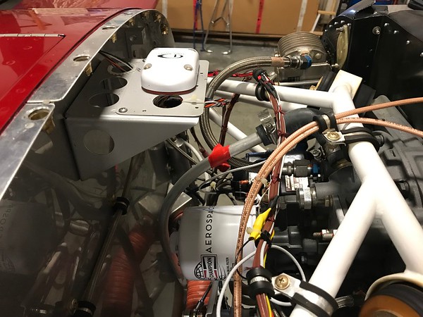
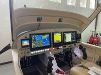
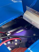
In the past I have been asked about how my antennas work mounted on a shelf under the cowling and the only answer I was able to give was "seems to work ok". I am glad nobody asked for a better data driven answer and so today wanted to explore different GPS antennas and how they performed in different locations. Since I am not a EE (I am a Chem E) so if anyone has input to the best way to judge signal strength let me know. My set-up is Garmin GDU 460's with a G5 and a GTN 750 in the middle. (See pic) I have the typical WAAS Garmin antenna on the 750 and a GA26C running to the PFD. For this test I added a: https://www.mouser.com/ProductDetail/Taoglas/AA.105.301111?qs=WUa1z/NV9%2B0Zz8quINyrVQ== for less than 15 bucks, recommended on this Forum to the MFD using a 
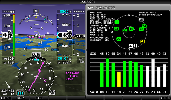
https://www.ebay.com/itm/401288401409 adapter for another 5 bucks. To judge resolution I looked at PDOP (Position Dilution of Precision) data that's on the Garmin SD card in each of the GDU's along with the number of sats captured. I wanted to see the difference in precision top cowling on and off. I did this on the ground with the antennas getting a clear shot of the sky outside my hangar. For the 750 it reports HDOP and did not count the sats displayed. For PDOP and HDOP the lower the number the better. (I have been told that anything under 2.0 is more than adequate, antenna engineers chime in)

Cowling Off: (Let it warm up for 5 mins and then took 5 mins of data)
PFD: PDOP-1.47 SAT-10.63 (GA-26C Ant)
MFD: PDOP- 1.38 SAT-10.89 (Taoglas Ant)
750: HDOP-0.8

Cowling On: (Same test procedure as above)
PFD: PDOP- 1.62 SAT-10.35 (GA-26C Ant)
MFD: PDOP- 1.42 SAT-10.74 (Taoglas Ant)
750: HDOP-0.9

To insure the GDU's did not bias the results I swapped antenna's and got roughly the same numbers as above. I also swapped the GA-26C for a GA-26X (Using that in the 10) and got pretty much identical results.

At the end of the day I attached the Taoglas antenna to the G5 (I did not have a GPS antenna on the unit) and was depending on the G5's internal antenna to provide a signal. Without the antenna attached my satellite reception was terrible and even with the cowling off could not lock on one satellite. With the antenna attached I was able to lock on 7 satellites. I ended up coiling the excess antenna cable up and attaching the Taoglas antenna to the top of the GDU460. Would be interested in hearing how other G5's are working without a GPS antenna attached.

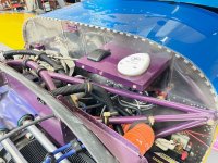
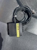
Note the Taoglas GPS antenna has about 1/4 the footprint as the GA-26C. I would rate this antenna every bit as good as the Garmin GA-26 series. Also, when I added or removed an antenna, I changed the software to let the GDU unit it had a antenna attached. The G5 unit did not have this option or at least could not find it.

I also pulled up data pre-paint (my paint has a pretty heavy metallic additive) and the PDOP's where almost the same before paint and after along with SAT count.
 

Attachments

  • Screenshot 2023-07-03 171034.jpg
    Screenshot 2023-07-03 171034.jpg
    167.6 KB · Views: 81
  • Screenshot 2023-07-03 170959.jpg
    Screenshot 2023-07-03 170959.jpg
    118.4 KB · Views: 86
Last edited:
Not to say that your tests are invalid, but DOP is almost entirely based on geometry, not signal strength. As long as the antennae "see" the same set of satellites and lock onto them, you'll get about the same DOP. With 8-10 satellites or more in view, a difference of one or two satellites won't make very much difference.
 
The reason that you can't just plug GPS antenna A into system B is that these things aren't JUST antennas. They have electronics in them !!!

this is unlike COM and VOR antennas where you can mix & match. Those literally are just an antenna... no electronic magic inside.

Which brings up point #2... putting electronics FWF... So would you mount your remote transponder / comm in the Engine Compartment?

Regarding GPS antenna actual temp limits... a quick search found https://vansairforce.net/community/showthread.php?t=195985&page=2

And for every "works fine for me" I say, yeah Columbia launched a bunch of times and "worked fine". OK, nobody remembers that. Fine... the Titan made multiple dives and "worked fine". I do not dispute or disrespect your individual success, but if you are exposing an electronic component to temperatures outside of its specs, it will do it no good.
 
A couple of observations.
I have the little GA26s on the glareshield.
One is for the G3X (via GDU PFD) and the other is direct to the G5
The G5 internal antenna in my setup is not great, so to ensure it had an adequate antenna I used one. They’re cheap as chips.
It gets mighty hot on that glareshield in the summer with the plane parked on the ramp.
I’ve had one of the GA26s fail. Was it heat? I don’t know. That’s consumer grade electronics.
It’s quite possible it may actually be cooler under the cowl than on the glareshield.
That said, have my IFR GPS antennas installed IAW the install manual, outside, on top with a clear view in all directions. I don’t want them to stop working unexpectedly.
 
Last edited:
Electronics FWF and GPD documented temp limits

The reason that you can't just plug GPS antenna A into system B is that these things aren't JUST antennas. They have electronics in them !!!

this is unlike COM and VOR antennas where you can mix & match. Those literally are just an antenna... no electronic magic inside.

Which brings up point #2... putting electronics FWF... So would you mount your remote transponder / comm in the Engine Compartment?

Regarding GPS antenna actual temp limits... a quick search found https://vansairforce.net/community/showthread.php?t=195985&page=2

And for every "works fine for me" I say, yeah Columbia launched a bunch of times and "worked fine". OK, nobody remembers that. Fine... the Titan made multiple dives and "worked fine". I do not dispute or disrespect your individual success, but if you are exposing an electronic component to temperatures outside of its specs, it will do it no good.

Good input and always worth reviewing the data. Over the last 10 years we have all noticed the additional electronics that are being placed FWF from electronic mags to coil packs to Lithium batteries (Which I have both) to now even generators mounted on the vacuum pads. (Electronic unit) This is actually one reason I like my B&C alternators as I can mount the VR on the cold side of the FWF. Yes, all of these typically use some sort of blast tubes (except coil packs) but what happens when you shut the engine down? For my set-up I monitor the temps in the FWF in the upper part and the lower part of my FWF compartment using thermocouples attached and data logged to my EFIS. Even in the Florida summer and with a heat-soaked engine I've never seen the FWF upper thermocouple exceed 125 F. (Normally see a delta T of 25 F max FWF to OAT) The next question is what the temps are when the engine is shut down inside the FWF. Since I don't like to run my EFIS after I shut it down placed these strip temp monitors (Over a year ago) in strategic parts of the FWF. The one mounted slightly below the GPS tray measures a max temp of 149 F. (It tripped the 140 but not the 150 F mark) Now what is a GPS rated temperature by the supplier? While I could not find that information for the GA-26 I did find other Garmin GPS antennas where they rated it at 176 F while other brands rated there's at 185 F. Garmin does rate the actual WAAS electronic box at 131 F but I could not find anything on the electronically filled and ultra delicate electronics inside a WAAS GPS antenna.

So, on the glare shield temps which Garman does authorize. Today I placed a Garmin GPS antenna under a glass bowl outside and within 5 mins the temperature had reached 160 plus and below 170 F. Ambiant conditions where 90 F. As one post mentioned these glare shield mounting seems to get every bit as hot as FWF. There are times when I cannot even touch my seat harness buckle. :mad:

So, what does the temperature get to of a properly installed Garmin WAAS antenna mounted on an aluminum plate exposed to direct sunlight? I'll bet you my under the cowling mount stays cooler.......;)
 

Attachments

  • battery temp 1.jpg
    battery temp 1.jpg
    527.8 KB · Views: 55
  • GPS Tempa 1.jpg
    GPS Tempa 1.jpg
    1.4 MB · Views: 62
  • GPS glass.jpg
    GPS glass.jpg
    1.4 MB · Views: 49
Last edited:
See Garmin data for a WAAS antenna

Was able to find what I think applies to our antenna's. 85 C is 185 F.
 

Attachments

  • Screenshot 2023-07-04 132820.jpg
    Screenshot 2023-07-04 132820.jpg
    50.7 KB · Views: 60
  • GA37GPS_WAAS_XM-antenna_EnvironmentalQualificationForm.PDF
    18.2 KB · Views: 133
Coil Packs

Every coil pack I'm familiar with is just that... a coil of wire. So long as you don't get to the point of melting it's wire insulation (typically enamel), it will be fine.
 
Back
Top