What's new
Van's Air Force

Don't miss anything! Register now for full access to the definitive RV support community.

GEA 24 Master Warning

TASEsq

Well Known Member
Patron
I have purchased a couple of illuminated switches to use as a master warning / master caution switch light to make use of the new g3x functionality in the latest software revision.

The g3x manual under the GEA24 section has a note:
“ 17. WHEN A DISCRETE OUTPUT IS ACTIVE, IT IS PULLED TO GROUND AND CAN SINK UP TO 20 MA OF CURRENT MAXIMUM. SEE THE G3X INSTALLATION MANUAL FOR ADDITIONAL DETAILS ON USE OF DISCRETE OUTPUTS.”

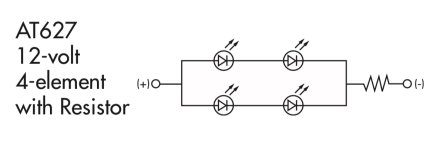
The switch I purchased is this one:
https://www.digikey.com.au/en/products/detail/nkk-switches/LB25RKW01-5D12-JD/2104983

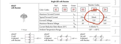
The spec sheet for the version of the switch I got says “typical forward current 26ma”.

Is 6ma extra going to be a problem for the GEA24?

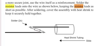
Do I need to add a resistor? (I have no idea how to work out what size).
 

Attachments

  • 45B7FF0B-44B4-4598-A74A-EBBDFAFF6B15.jpeg
    45B7FF0B-44B4-4598-A74A-EBBDFAFF6B15.jpeg
    195.9 KB · Views: 54
Last edited:
I can't answer how much is too much current. You can get a micro relay to deal with it. Pretty sure they are under 20mA. I would also check further on the specs. I believe those two caution/warning feeds are dedicated and don't use the Discrete's and likely have higher amperage ratings. Pretty sure it would be designed for incandescent bulbs, which draw a lot more than 20 mA.
 
Last edited:
Small resistor

Start with a 4.7ohm, then move to 2.2ohm if the brightness isn't sufficient.
 
I get a different answer. The center diagram (for 12v) shows there are two parallel legs each with 2 LEDs and then a single resistor in series. The voltage drop across 2 diodes in series will be about 4v (depends a bit on the color but 2v per LED is a good starting point for red/orange/yellow). That leaves 8v across the resistor at 0.026 amps, so the internal resistor is in the region of 300 ohms. If you want to halve the current, you'll need another 300 ohm resistor in series. I suggest halving the current, so you have a bit in reserve to cope with the ~14v you'll see on your bus.
 
Pretty much any general purpose PNP transistor, configured as an emitter follower, will do what you want.
 
From the G3X manual rev AS page 22-31:
Sink current must be externally limited to 20 mA max.
U (volt) = I (current) x R (resistance).
The switch you have limits current to 26 mA, which is to much for the GEA24.
This means that your switch has internal resistor of 14 V / 0.026 = 538 ohms or so.
To be safe, do not exceed 75% of the max value 20 mA for the GEA 24.
Engineering value (15 mA).
(14 / 0.015 = 933 Ohm. Choose a 1 kohm resistor).
You already have a internal resistor of about 538 ohm.
To limit the current to 15 mA you need one extra resistor of 500 ohm in series.
The resistor should be capable of a power of 0.015 A x 14 V = 0.21 W.
Choose a 0.25 W resistor.

Good luck
 
Last edited:
As explained in an earlier post, the forward voltage drop of the LED's means the voltage across the resistor is not 14V.
 
I’m building my -14 for educational purposes - and I certainly learn every day!

Thanks for the replies - been very helpful, and prompted me to do a bit of reading.

I’m going to assume a 14v source, and also a 2 Vf drop for each LED.

Since the LED’s are configured as 2 series runs of
2 in parallel, the voltage drop would be 4v across the + / - terminals so the resistor would see 10v

10v / 0.026ma = 384 ohm. (390ohm)

Since the GEA24 can only sink 20ma, or say 16ma with a buffer then 10v / 0.016ma = 625 ohm is needed.

Minus the 390 ohms already in the switch I need a 235 ohm resistor? (220 or 270 ohm).

Does my high school electronics understanding work out?
 

Attachments

  • 65C5BDCD-0F2F-4124-811B-BB122346831E.jpeg
    65C5BDCD-0F2F-4124-811B-BB122346831E.jpeg
    80.6 KB · Views: 11
Minus the 390 ohms already in the switch I need a 235 ohm resistor? (220 or 270 ohm).

Does my high school electronics understanding work out?

Yes. You understand that you'll be giving up some brightness from the LED.

Maybe it's okay for a "Master Caution", but unless there's some sort of dimmer involved this thing is likely to be annoyingly bright at night.
 
Trent, you've mastered this very quickly, but one tiny mistake. When you calculate the resistance built into the device, you need to use 12v (not 14), because that's the spec, which will give you 300 ohms. Then your calculation at 14v/0.016A is correct but you need to subtract 300 ohms instead of 390, so you'll get 325 (330) ohms for the additional resistor.
 
Trent, you've mastered this very quickly, but one tiny mistake. When you calculate the resistance built into the device, you need to use 12v (not 14), because that's the spec, which will give you 300 ohms. Then your calculation at 14v/0.016A is correct but you need to subtract 300 ohms instead of 390, so you'll get 325 (330) ohms for the additional resistor.

Makes sense **headslap**

Next question is how to physically install the resistor. I will have 2 of these switches, so I was thinking of soldering some 22 awg to each end of the resistor, and covering it with heat shrink - one end will go to ground and the other end into a ring terminal to one switch, with a jumper out of that to the other switch. Aka - the switches would share the resistor.
 
Yes. You understand that you'll be giving up some brightness from the LED.

Maybe it's okay for a "Master Caution", but unless there's some sort of dimmer involved this thing is likely to be annoyingly bright at night.

Haha true.
I went down a bit of a rabbit hole converting an incandescent illuminated DPST rocker into an LED illuminated rocker. It worked out really well!
First night landing… fuel pump on… yikes! Illuminated the entire cabin.
Thankfully it’s mounted near the throttle quadrant. So I just put my cap over it. If it was on the panel I’d have had to turn it off.
I never considered dimming it before then.
 
Aka - the switches would share the resistor.

Nope, that will cause the brightness to reduce if both the master caution and the master warning are on compared to just one of them on. You'll need a separate resistor for each switch.

I also agree with Richard - you will need a means of dimming these if you are going to fly at night.
 
Nope, that will cause the brightness to reduce if both the master caution and the master warning are on compared to just one of them on. You'll need a separate resistor for each switch.

I also agree with Richard - you will need a means of dimming these if you are going to fly at night.

Ok - one for each is in case both lights are on at the same time they would only see half of the resistance each?

They are a master warning / caution light. I wasn’t planning on running them through the dimmer circuit. They shouldn’t be on during normal ops.
 
Is this also the best practice method for including a resistor? Seems like a weak point in the wiring to me and this seems sensible.
 

Attachments

  • FA1BE8DC-6C3B-4D61-AC01-99B64E2208CF.jpeg
    FA1BE8DC-6C3B-4D61-AC01-99B64E2208CF.jpeg
    168.2 KB · Views: 23
Ok - one for each is in case both lights are on at the same time they would only see half of the resistance each?

They are a master warning / caution light. I wasn’t planning on running them through the dimmer circuit. They shouldn’t be on during normal ops.

Each to their own but for me there’s limited utility in having additional lights.
The CAS system is plenty adequate to visually and aurally tell you what’s going on if something needs alerting. I had them on my RV7 but didn’t install them for the 10.
If you are planning night or IFR ops and they are on the panel then they must be dimmable under the regs in Aus.
Are you planning on night or IFR ops? If so perhaps PM me.
 
You can use a 1/4w or 1/2w axial resistor. The larger wattage resistor is physically larger so it would be more durable if you are worried about that even though the wattage is not required. What I did was use 1/4w resistor, trim the leads to about half an inch and solder the leads to the wire. I covered the entire assembly with clear heat-shrink.
 
You can use a 1/4w or 1/2w axial resistor. The larger wattage resistor is physically larger so it would be more durable if you are worried about that even though the wattage is not required. What I did was use 1/4w resistor, trim the leads to about half an inch and solder the leads to the wire. I covered the entire assembly with clear heat-shrink.

This was the one I was thinking - very $$

https://www.jaycar.com.au/330-ohm-0-5-watt-metal-film-resistors-pack-of-8/p/RR0560
 
Last edited:
Back
Top