Dad's RV-10
Well Known Member
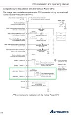
Installation includes G3X, VP-X, VP PPS and B&C 60 amp alternator.
The GEA24 is connected to the Alternator Current pins on the Vertical Power PPS (pin 18 & 19). "Shunt 1" in the G3X config is selected to "Alternator Amps." The indicated amps appear to be considerably higher than what would be expected. The amp indication is also showing 4 amps with the engine not running. I would assume this should be Zero?
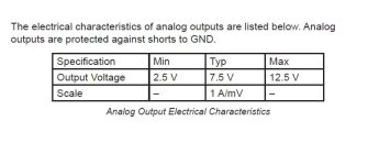
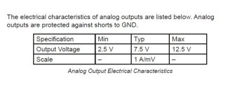
I think the G3X Scale Factor needs to be adjusted but I'm not 100% what value to set. The PPS manual has a small chart that shows "Scale 1 A/mV."
In the Shunt 1 Calibration menu, the default Scale Factor displays Multiplier 1.00. When changing the Scale Factor drop-down from "Multiplier" to "mV/Amp," the default value is .50. The displayed Sensor Values differ depending on wherever Multiplier or mV/Amp is selected.
I'm not sure if I'm interpreting the info in the PPS manual correctly but I tried temporarily selecting Scale Factor to "mV/Amp" and setting 1.0 vs. the default .50. That changed the Calibrated Value from 4.0 to 2.0.
I'm not sure this is how I should have the Scale Factor set? If it is the correct setting, I would guess I'd need to adjust the Zero Offset to -2.0 to zero-out the displayed 2 amps?
Any help is appreciated.


Last edited:


