What's new
Van's Air Force

Don't miss anything! Register now for full access to the definitive RV support community.

elevator travel question?

jscottpilot

Active Member
To get the required up deflection of the elevtor I had to trim the aft deck and control stop alot. The elevator horns are within a hair width of touching the F-812A Bulkhead to achieve this travel. For the down elevator travel I do not need to trim any off of the horizontal stab channels and the horns do not touch the down elevator stop at all to get the necessary travel. Has anyone else had this experience.
 
One way.....

I wanted to achieve maximum UP elevator deflection. In order to do that, using a rotary file fitted to a die grinder, I removed a substantial amount of the up elevator stop. I also had to shave just enough material off the corners of the elevator horns to achieve positive clearance with the F-812 bulkhead when the elevators are deflected a maximum 30 degrees up.

As your experience, the horns do not touch the elevator down stop at maximum down deflection. I'm still thinking about a fix for that one.

 
Rick,
My up "notch" looked like yours but mostly on the right side. I cannot believe that they weld these elevator horns in a jig as mine are out about 3/8" when the elevators are neutral. Down max deflection was right on the stop for me, but on the left horn only because of the mis-alignment:mad:
 
The only fix that I can think of for the rudder downstop is to just build a bigger rudder down stop that reaches the same distance as the horizontal stab channel
 
As your experience, the horns do not touch the elevator down stop at maximum down deflection. I'm still thinking about a fix for that one.

Rick,

Just curious -- What did you end up doing with your "down" stop? Did you just fabricate one and attach it to the rear deck?

My elevator horns don't even come within 1/4" of the down stop already installed on my QB fuselage.

I addressed this question to Rick, but if anyone has suggestions here, I'd love to hear them. Thanks!
 
Rick,

Just curious -- What did you end up doing with your "down" stop? Did you just fabricate one and attach it to the rear deck?.....
Buck,

Because of limited space, I had to remove the elevators in order to shoehorn the airframe in my cramped garage and have not yet addressed the elevator down stop, but I know what I am going to do after the move to the airport. From my perspective, there is no need to do anything with the down stop on the rear deck which would be difficult for me to rework since the vertical stab is permanently bolted into place and I have little enthusiam for removing that assembly to gain better access when an easier solution seems perfectly feasible.

What I will do is simply attach a spacer of required thickness to the forward edge of an elevator horn. It is that spacer that will make contact with the down stop on the rear deck.
 
Last edited:
Same issue

I wanted to achieve maximum UP elevator deflection. In order to do that, using a rotary file fitted to a die grinder, I removed a substantial amount of the up elevator stop. I also had to shave just enough material off the corners of the elevator horns to achieve positive clearance with the F-812 bulkhead when the elevators are deflected a maximum 30 degrees up.

As your experience, the horns do not touch the elevator down stop at maximum down deflection. I'm still thinking about a fix for that one.


Rick,

I am at this point with my QB -8A. The horn does not hit the down stop at max travel. How did you attach something to the elevator horn to bridge the gap, rivets I assume? Mine is about 3/32 from the stop at max travel. I came to VAF because I was getting uncomfortable with how much I thought I would need to trim the aft stop to get the max up elevator travel. From reading this it seems common for this to happen. Thanks

Cheers
 
Mike,

I was going to use a small length of .060 thick 90? angle stock for the elevator stop.....actually just a section of aluminum cut away from a long ago scrapped instrument panel blank that includes the necessary 90? bend.....and simply rivet it into place on the horn using 2 AD4 rivets. Turns out I really did not have to....at maximum full forward (down) travel, the co-pilot's joystick grip touches the back of the pilot's seat.
 
I guess I will wait

Thanks for the quick reply. I was thinking of maybe turning the bearings in one turn on the elevator but that would put the leading edge of the elevator very close to the rear spar. With the bearing set according to the plans I have about 5/32 clearance. I think I will do like you did, trim to the max travel limit for the up side and modify the horn as required and wait to see about the down limit once everything is hooked up. Don't you just love these little nuggets!

Cheers
 
Turns out I really did not have to....at maximum full forward (down) travel, the co-pilot's joystick grip touches the back of the pilot's seat.
The control travel stops need to be AT the control surface, not at the other end of the linkage. If the stop is at the stick and some outside force pushes the control surface the linkage can become damaged.
 
Why doesn't Van's fix this

I have read over several RV-8 builder sites and almost everyone has the same issue The elevator does not hit the down stop at the max down travel limit, and you are doing this after the stop has been fabricated according to the plans and installed. To get within the up limit minimum you have to trim the aft deck to the point that the elevator horn is close if not touching the aft bulkhead. To get max up travel the elevator horn must be trimmed.

So this begs the question, with as long as these kits have been around why doesn't Van's at least put out notes so that when you are building the down stop you can make it a bit longer and then trim as required. These kits are pre-punched. I have a QB but my kit mistakenly came with the pre-punched angles for these stops, you can't make them longer.

So does Van's really want you to have the 1.5 degree (that is what it does for my plane) of extra down travel but don't want to publish this? There are not a lot of issues like this but there have been a few, if so many builders find these things Van's must be getting calls, so why not issue some builder notes with the kits.

The other nugget I have now read about on other sites is trimming the VS forward spar, if you trim to the plans dimension you will end up with less than optimal edge distance on the bottom rivets. When I called about this to Van's the first guy said, you can see from the DWG that it is planned for minimum ED. I did not say anything then but, I thought why plan for minimum ED on a part that you control how much gets trimmed off! Oh well I guess it all make us better builders.

Cheers
 
Last edited:
I have read over several RV-8 builder sites and almost everyone has the same issue The elevator does not hit the down stop at the max down travel limit, and you are doing this after the stop has been fabricated according to the plans and installed. To get within the up limit minimum you have to trim the aft deck to the point that the elevator horn is close if not touching the aft bulkhead. To get max up travel the elevator horn must be trimmed.

So this begs the question, with as long as these kits have been around why doesn't Van's at least put out notes so that when you are building the down stop you can make it a bit longer and then trim as required. These kits are pre-punched. I have a QB but my kit mistakenly came with the pre-punched angles for these stops, you can't make them longer.

So does Van's really want you to have the 1.5 degree (that is what it does for my plane) of extra down travel but don't want to publish this? There are not a lot of issues like this but there have been a few, if so many builders find these things Van's must be getting calls, so why not issue some builder notes with the kits.

The other nugget I have now read about on other sites is trimming the VS forward spar, if you trim to the plans dimension you will end up with less than optimal edge distance on the bottom rivets. When I called about this to Van's the first guy said, you can see from the DWG that it is planned for minimum ED. I did not say anything then but, I thought why plan for minimum ED on a part that you control how much gets trimmed off! Oh well I guess it all make us better builders.

Cheers

Its now 2023, and I still don't see Vans update the documentation on the RV8 for some of these issues. They are so, so good in so many ways, but documentation improvement is an ongoing process, not a done and move on to the next design kind of thing. I encourage the documentation and engineering team to think in terms of continuous improvement. Just because they are the best out there, doesn't mean there aren't a few opportunities to keep improving. Just a viewpoint from the peanut gallery and very loyal but occasionally frustrated builder. :)
 
Thanks goodness I ran across this thread. At first I thought I had really screwed up and was about to lose my sanity. I did have to pull the horizontal stab to get good access to make a down stop and grind away the up stop. Also the elevator horns may need some grinding.

Onward thru the fog……
 
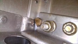
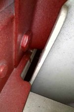
For anyone thinking "I'll just leave it, it doesn't matter", the first items checked on a good prebuy are both under the empennage fairing...the elevator stops and the front spar drilling to the longerons.

The most recent prebuy offered fine examples of both sins.

IMG_0006.JPG

IMG_0017.JPG
 
For anyone thinking "I'll just leave it, it doesn't matter", the first items checked on a good prebuy are both under the empennage fairing...the elevator stops and the front spar drilling to the longerons.

The most recent prebuy offered fine examples of both sins.

View attachment 66185

View attachment 66186
The fundamental sin in the first pic is the Van's design that is extremely unforgiving of any error by the builder. There is very little if any tolerance for the location of that bolt hole through the longeron, in order for all edge distances to be respected. Access is difficult during construction. It is not surprising that airframes have been built with problems in this area. I recall cutting and shaping the transverse angle at least three times before getting it "right".
 
Yup! My first part was cut with enough room for longerons, not thinking about the many steps ahead. Second time I custom fit it in. Funny, inspecting tech counselor went right there. I said, I got it right the second time.
 
The fundamental sin in the first pic is the Van's design that is extremely unforgiving of any error by the builder.
...which does not excuse the acceptance of sloppy work. My compliments for doing it over and getting it right.
 
The fundamental sin in the first pic is the Van's design that is extremely unforgiving of any error by the builder. There is very little if any tolerance for the location of that bolt hole through the longeron, in order for all edge distances to be respected. Access is difficult during construction. It is not surprising that airframes have been built with problems in this area. I recall cutting and shaping the transverse angle at least three times before getting it "right".
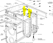
I was pretty nervous about building this section because there was zero tolerance for edge distance. One wrong drill hole and the longerons could be ruined. I was also having a hell of time bolting my horizontal stabilizer to the longerons because there isn't much room for a grown person with a big arm to put the nut in the initial thread of the bolt. I wish Vans had modified the design so that he horizontal stabilizer can be bolted in shear instead of in tension. This will remove the chance of making the edge distance error. For reference, look at how the rear spar of the horizontal is bolted in shear
1720540840654.png
 
Back
Top