Hello everyone, I must call upon you guys one more time to look over my electrical diagram.
This diagram is Bob's Z-13/8 with VERY FEW modifications. I'll point them out in the pics below.
First here are the pics, sorry they are so big but I'm thinking this is the only way you will be able to read anything.
I am aware of how to size wires per AC 43.13. However, I went with what the manufacturer recommended instead
(which was always bigger than AC43.13 or right on). This is why I have at times two different gauges for the same circuit size.
Yes I know in most instances I can use 22 awg where I speced 20 awg. I already have plenty of both sizes so no worry there.
Would you all mind taking some time to look it over for any blatant errors? Mega thank you for taking the time.
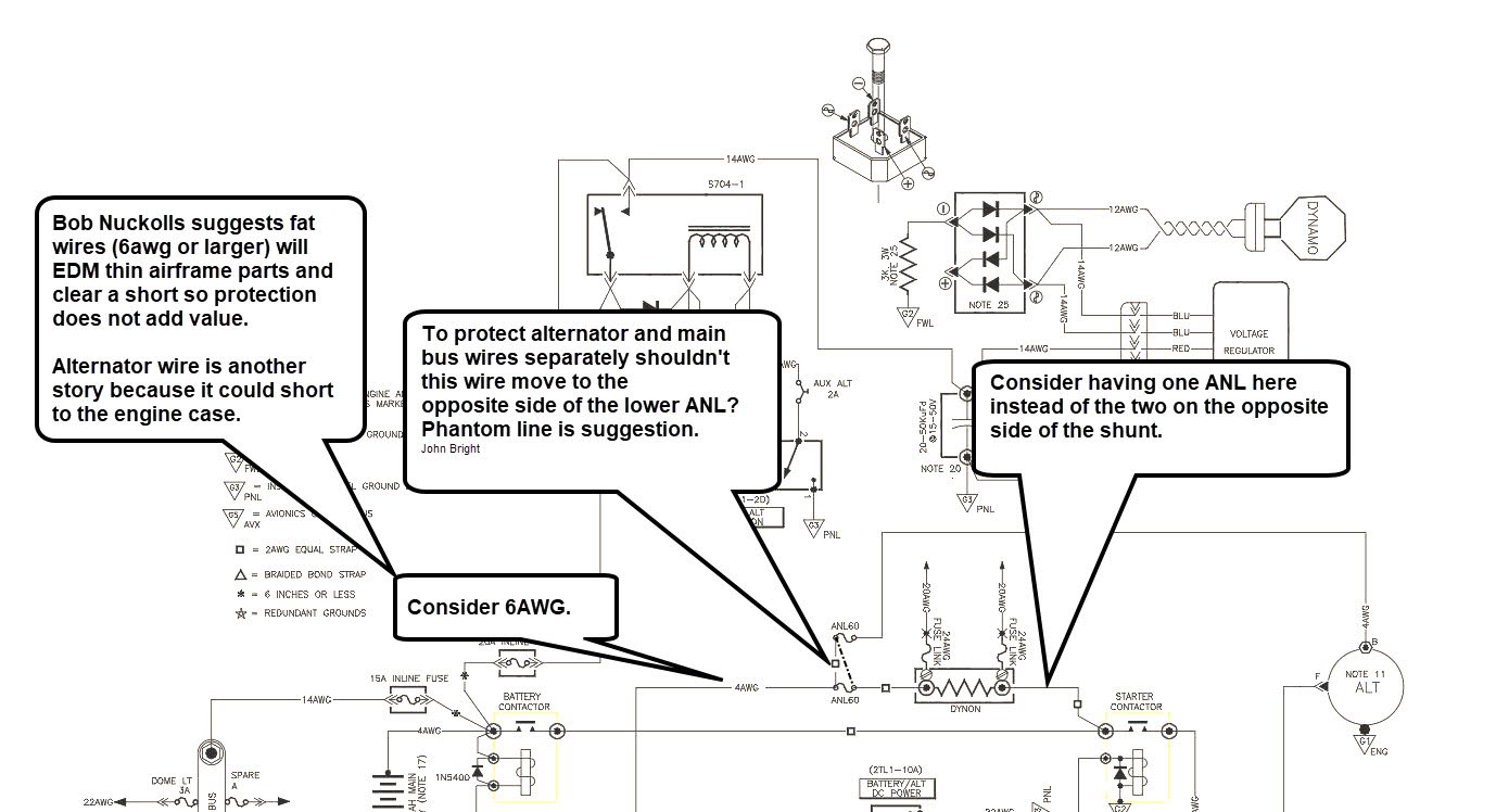
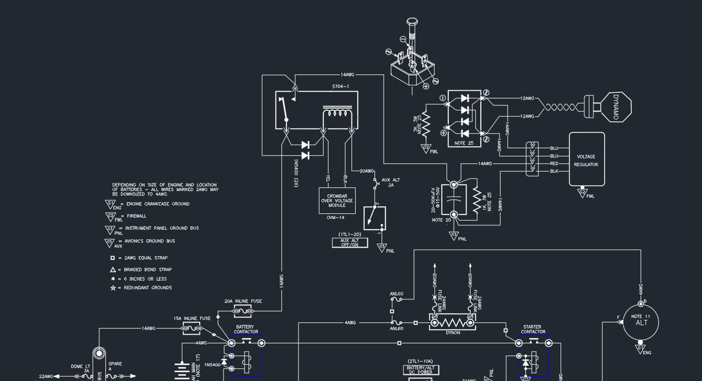
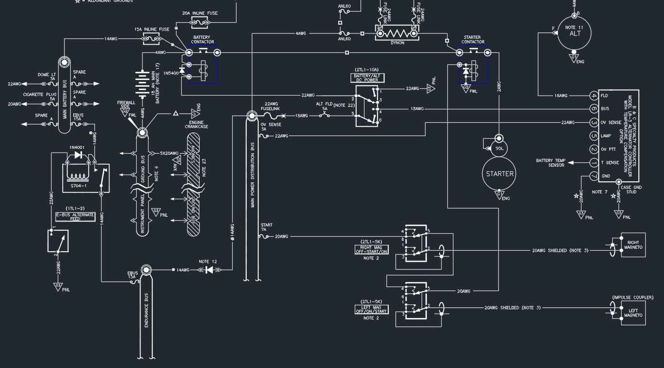
First up is the top of the diagram where the backup B&C SD-8 is.
The changes here are the shunt and ANL positions. I have already
installed two ANL fuses on my firewall as I would prefer both battery
and alternator lines be protected. Many find it unnecessary which may
be the case but it's already done and installed. I have also removed the
shunt for the backup alternator because if I am ever running on it I will
know my e-bus is sized right for the current and I can simply monitor bus
voltage. If you REALLY think I need a shunt give me a good reason and I
may install one but at this time I don't see the point. Finally, my main
shunt will let me see current as pertains to battery charging or discharging.
This is one of Dynon's 3 recommended methods.
 1 by Jereme Carne, on Flickr
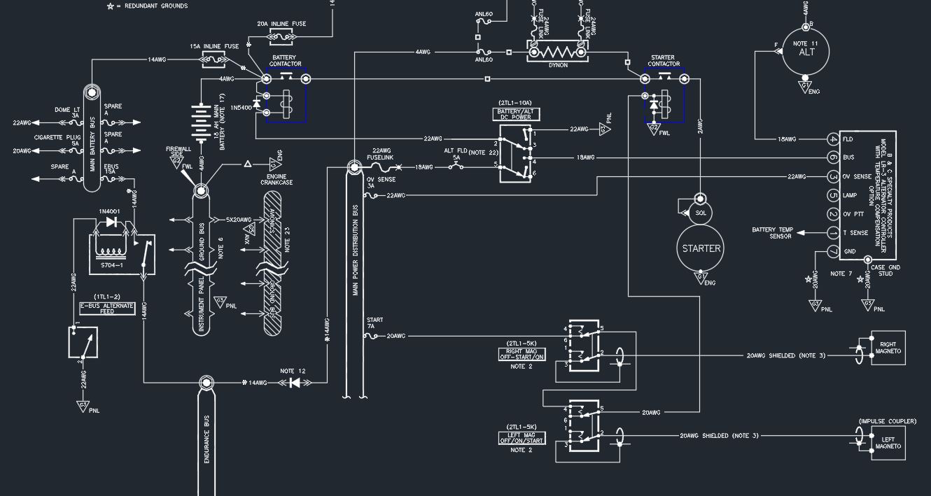
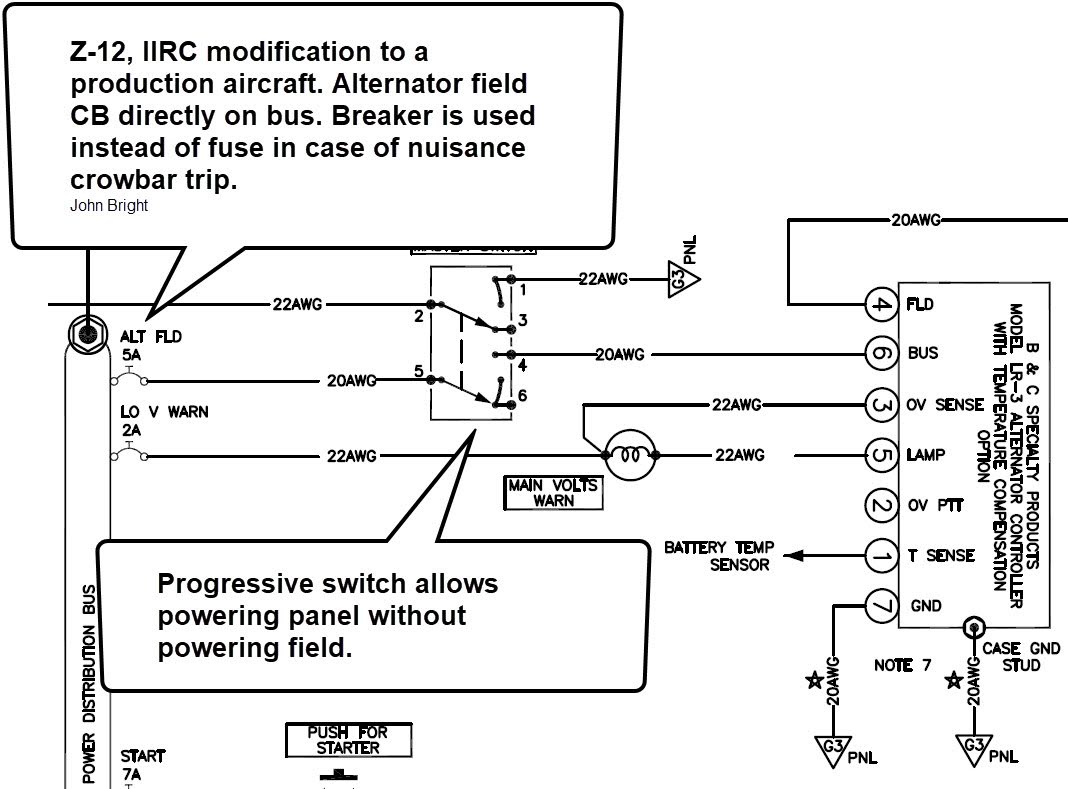
Next up is the lower meatier part of the diagram. I eliminated the electronic
ignition and put in for mags instead. I know many like having a dedicated
start button but I really like the left mag also being your start switch. This method
is also wired such that the right mag must be off to send power to the starter. As far as
mag switches and the batt/alt switch they are locking toggles. The mags lock in off and
on with momentary up. The batt/alt switch locks in all three positions. All switches are
Honeywell TL series. You will also notice that I changed to a B&C main 60amp
alternator and eliminated the low voltage lamp since Dynon will do this on
its own. Also, the battery bus only has a cigarette USB plug and a dome
light on it. Finally, Bob shows a 20awg wire feeding the E-bus from the main
bus which seemed quite small to me. I up sized it to 14awg.
 2 by Jereme Carne, on Flickr
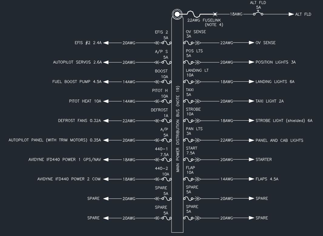
On to the buses. Here is the main bus. I also tried to include any future
provisions such as the second EFIS even though I don't currently plan it.
The IFD-440 however is in the plan and I'm installing a tray for it now. You
will also notice the amp numbers on the right side of the description. This is
what I could find for MAXIMUM current draw on the device.
 main by Jereme Carne, on Flickr
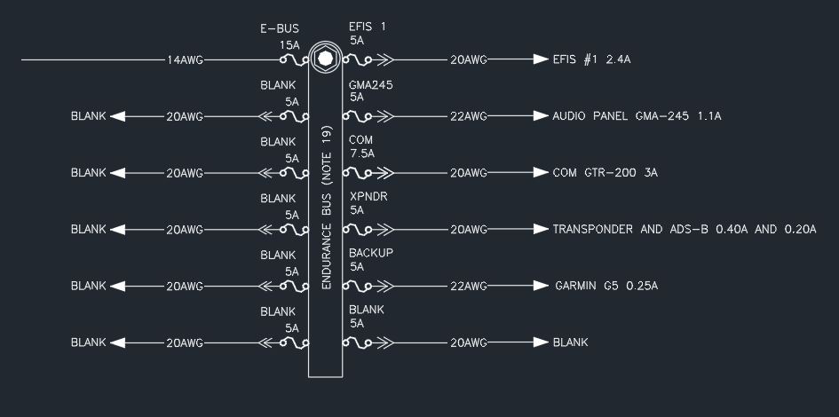
Now the E-bus. I really tried to minimize what I put on this to the essentials but really the end goal was to keep it below 7 ish amps
(which is why the xsponder is still there) So far the MAXIMUM current amounts add up to 7.35 amps not including the contactor
which is fairly low. (the master at this point would be off so don't worry about that 1 amp) At 2500 engine RPM by the B&C numbers
you should get about 7.6 amps. It's also worth noting that in my emergency checklist for this situation I would
unplug/turn off everything on the battery bus.
 ebus by Jereme Carne, on Flickr
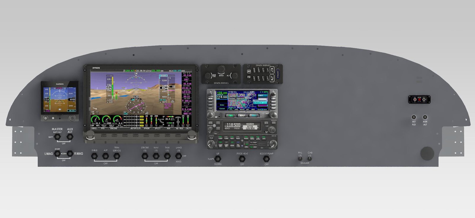
I also am posting the picture of my panel layout if that helps anyone.
 FINAL PANEL by Jereme Carne, on Flickr
Seriously thanks to everyone who helps me look over this big part of my project. As always if you have questions or comments I welcome it all!
This diagram is Bob's Z-13/8 with VERY FEW modifications. I'll point them out in the pics below.
First here are the pics, sorry they are so big but I'm thinking this is the only way you will be able to read anything.
I am aware of how to size wires per AC 43.13. However, I went with what the manufacturer recommended instead
(which was always bigger than AC43.13 or right on). This is why I have at times two different gauges for the same circuit size.
Yes I know in most instances I can use 22 awg where I speced 20 awg. I already have plenty of both sizes so no worry there.
Would you all mind taking some time to look it over for any blatant errors? Mega thank you for taking the time.
First up is the top of the diagram where the backup B&C SD-8 is.
The changes here are the shunt and ANL positions. I have already
installed two ANL fuses on my firewall as I would prefer both battery
and alternator lines be protected. Many find it unnecessary which may
be the case but it's already done and installed. I have also removed the
shunt for the backup alternator because if I am ever running on it I will
know my e-bus is sized right for the current and I can simply monitor bus
voltage. If you REALLY think I need a shunt give me a good reason and I
may install one but at this time I don't see the point. Finally, my main
shunt will let me see current as pertains to battery charging or discharging.
This is one of Dynon's 3 recommended methods.
1 by Jereme Carne, on FlickrNext up is the lower meatier part of the diagram. I eliminated the electronic
ignition and put in for mags instead. I know many like having a dedicated
start button but I really like the left mag also being your start switch. This method
is also wired such that the right mag must be off to send power to the starter. As far as
mag switches and the batt/alt switch they are locking toggles. The mags lock in off and
on with momentary up. The batt/alt switch locks in all three positions. All switches are
Honeywell TL series. You will also notice that I changed to a B&C main 60amp
alternator and eliminated the low voltage lamp since Dynon will do this on
its own. Also, the battery bus only has a cigarette USB plug and a dome
light on it. Finally, Bob shows a 20awg wire feeding the E-bus from the main
bus which seemed quite small to me. I up sized it to 14awg.
2 by Jereme Carne, on FlickrOn to the buses. Here is the main bus. I also tried to include any future
provisions such as the second EFIS even though I don't currently plan it.
The IFD-440 however is in the plan and I'm installing a tray for it now. You
will also notice the amp numbers on the right side of the description. This is
what I could find for MAXIMUM current draw on the device.
main by Jereme Carne, on FlickrNow the E-bus. I really tried to minimize what I put on this to the essentials but really the end goal was to keep it below 7 ish amps
(which is why the xsponder is still there) So far the MAXIMUM current amounts add up to 7.35 amps not including the contactor
which is fairly low. (the master at this point would be off so don't worry about that 1 amp) At 2500 engine RPM by the B&C numbers
you should get about 7.6 amps. It's also worth noting that in my emergency checklist for this situation I would
unplug/turn off everything on the battery bus.
ebus by Jereme Carne, on FlickrI also am posting the picture of my panel layout if that helps anyone.
FINAL PANEL by Jereme Carne, on FlickrSeriously thanks to everyone who helps me look over this big part of my project. As always if you have questions or comments I welcome it all!