Most importantly, it provides two separate current paths to the engine electronics that do not require pilot intervention to manage.
Bull. It drives a main and essential bus. There is no power path dedicated to engine electronics alone, and pilot intervention can be necessary.
The emergency power switch is a third level of redundancy on top of that.
The emergency power switch merely bypasses one of the Bus Master's relays. The only failures it can directly mitigate are the relay or the relay control circuits. As the key switch controls both main and essential relays in parallel, the real purpose of the "emergency"switch is to provide a way to shut down the main bus and still have power to the essential bus. Put another way, it's not a backup. It is required.
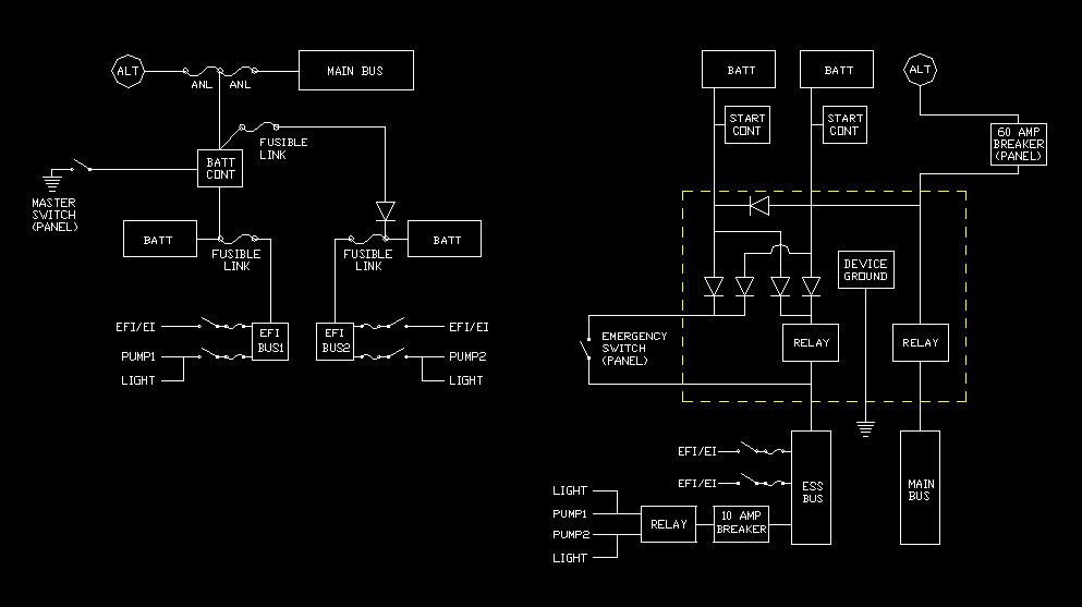
For most experimentals, the Bus Manager can serve as the power distribution for the entire aircraft. The Main Bus output powering non flight critical systems and the Essential Bus output powering the critical engine systems.
So, both ECUs and both ignitions are powered from a single essential bus, not the claimed "two separate current paths". Let's put a smoke smell in the cockpit. With the main bus shut down (key OFF), the only power path is through the "emergency" switch. Can't check that switch on the run up pad without shutting down all the main bus avionics, so it won't get checked very often, which kinda stomps a basic rule about checking equipment
required for flight.
We have close to 200 Bus Managers in the field. The only one that ever had a bus failure had one of its bus outputs shorted directly to ground during installation. (turn the power off when doing the wiring!).
Which nicely defines one of many failure modes. Or are we to believe that the same output can never get shorted in an airborne aircraft? When it happens, it's essentially a dead-shorted battery, so it melts the Bus Master's diodes, and/or relay(s), and/or "emergency switch", none of which are rated for anything like battery amperage. BTW, the switch requires running an unprotected 10 ga lead into the panel, and then back to the BM. Does that architecture increase the risk of a short?
There is no master solenoid near each battery. The large cable runs to the BM can't be disconnected. Same for the cables to the start solenoids. Stuck start solenoid? Sorry Charlie.
The fuel pump management is a great feature and works very nicely.
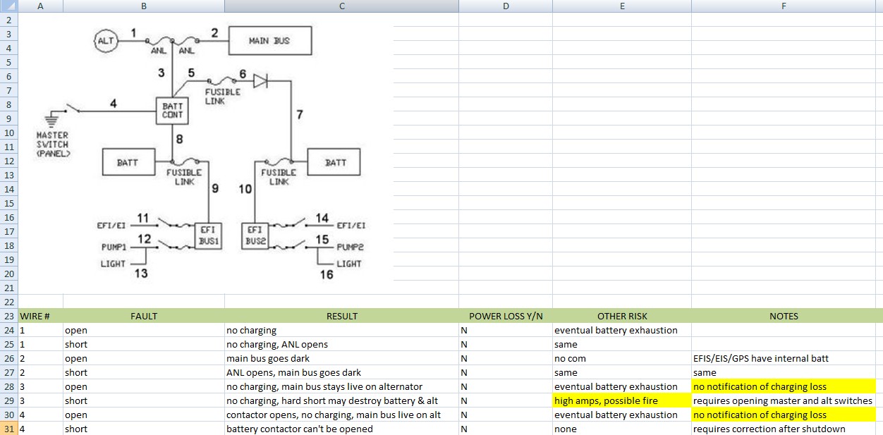
Both pumps are driven by the same single wire, breaker, and relay. A shorted primary pump annunciator circuit, a shorted pump power circuit, or a shorted pump motor will all pop the circuit breaker. Of course the BM will detect the loss of fuel pressure, but the "fully automatic pump management" can't make the second pump run until the pilot diagnoses the cause of his no-run condition, then finds and resets the circuit breaker. Good luck with that at 300 feet outbound over the trees, where the rest of us are simply running two very independent pumps.
BTW, the BM diagrams all use the standard diamond symbol for grounds, with no further details. The BM has a single ground; loss of that ground path opens the relays and makes everything silent. Restoring power will require diagnosis time, then finding and flipping the emergency switch...more fun out over the trees.
The text suggests grounding everything to a single point ground bus. Drawing 1 ties the ground bus to the batteries with a single 4 ga cable in parallel. I recently proposed something similar for my own airplane, and the gang quite correctly pointed out that terminal corrosion at the one shared battery negative post has the potential to shut down both ignitions. That is also true here, at Battery 2.
I can go on, but hopefully the point is clear. There is nothing very redundant about a Bus Manager, and it brings failure modes of its own. Some are not recoverable. Others require time and pilot input not always readily available.


")