Wade,
Like Marky-Mark, I think this is really cool work. It will be very interesting to see your test results. Can you post wider angle views of your inlets, and maybe a side-view of the exit with the nozzle installed?
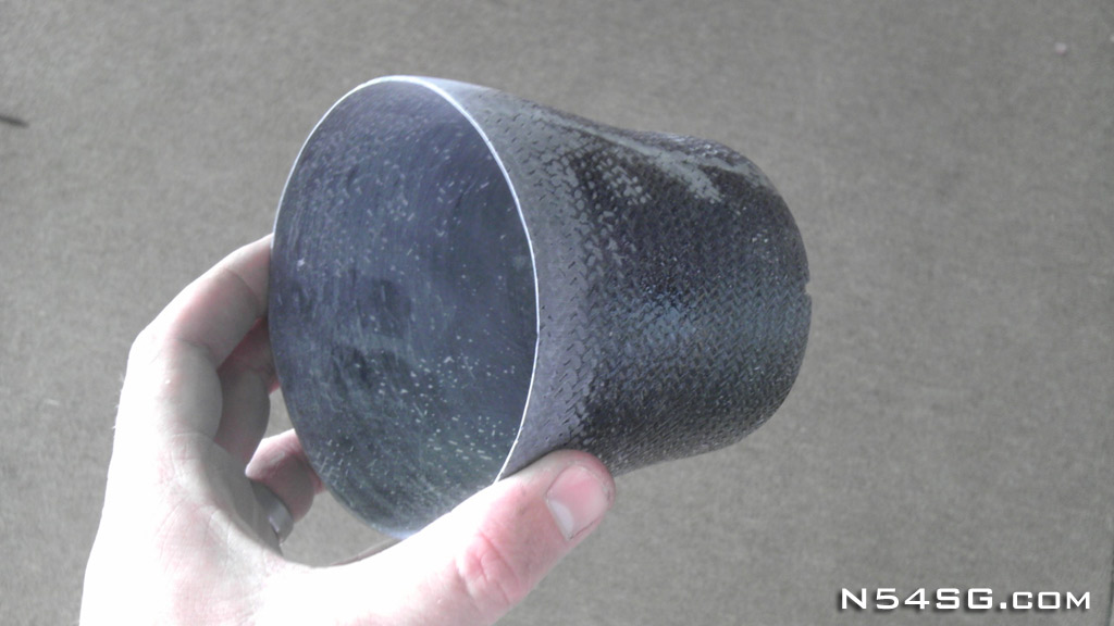
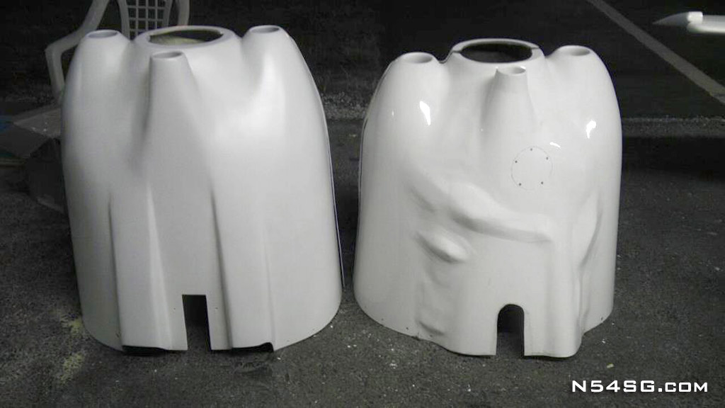
Thanks Bob, no worries, I take all input as constructive and enjoy the exchange of ideas that this forum facilitates. I am very appreciative of any input from those like you and Mark, who have tinkered in this area before. In the early picture above you can see the entire front cowl in foam, it looks the same today, except the left inlet has been opened up to become one hole. I will make sure and post the views you request when I have more info. You can also find pictures of my cylinder baffles on other threads, I keep the air in contact with the cylinder all the way around.
Can you share the thoughts behind your design decisions? I'm very interested in hearing the background.
I heard the stories about 200hp RV-8 and you "NEED" louvers, ect.. Set me to doing a lot of reading. It appeared plain to me that the stock inlets are actually oversized, which led to more thinking. Turns out 12 sq inches of area will keep 2 rows of a Lycoming below 300 deg with hard running at our speeds. Then came to realization that a "system" approach is needed. So my work is not just the exit, but the system as a whole. Sorry, I am rambling.
The cowl flap is the easiest (and most elegant if Dan is doing the work
")
) way to get variable cooling flow, but I did not want to have anything to control. Or maybe I hit my head as a child and like to do things differently, wait I did hit my head in 5th grade...
I have been intrigued by the idea of exhaust augmentation and trying to recover some of that heat energy that is otherwise wasted. In a general nutshell, my original goal was to size the inlets for cruise and use the augmentation to get good cooling in climb when airspeed is lower, no cowl flaps. Then in discussions with Paul Lipps I started thinking about actively trying to accelerate the exit air as well. I made a mold and am playing around with 4 or 5 different nozzle designs in my head to try out. No aero engineer, though I started out at UT on that path be before life got in the way.
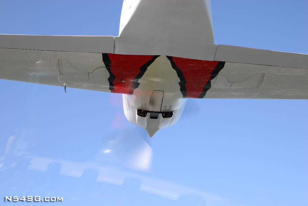
A couple thoughts…not criticisms.....The wetted area represented by the exit appears large…it drops down below the cowl quite a bit. Decreasing the circumference to decrease the downward protrusion may help. My visual SWAG is that you have more than enough cooling exit area, so may be able to go smaller.
The sides of the primary exit (forward of the removable nozzle) appear to converge, both as they move up towards the fuselage, and as they move aft. If you can get those sides parallel to the airflow, all the way till they end, it may enhance flow and decrease flow separation.
The sides of the removable nozzle, at the top, converge quite a bit. You made a nice trailing edge shape, but that convergence could cause separation. That area above the nozzle has a lot of interacting shapes…looks really cool, but might be a flow separation area.
It appears you are necking down the area with that nozzle…one option to consider might be bringing the shape up more from the bottom, rather than down from the top. That would decrease exit area, and wetted area, in one step.
The swale in the bottom of the scoop may be detracting too. The low point on the gray portion, near the clecos, may be forced on you by the exhaust…but if not, any way to decrease that bump and curve could be beneficial, from both a wetted area and airflow perspective.
I hear you, I have increased the wetted area. Darn compromises to get flying and not be too radical on an existing plan airframe to start. This shape is dictated by my exhaust system. I may change the angle of the collector to allow a much closer to the body configuration in the future. I was also worried about vibrations and heat on the bottom of the fuselage. For all of those reasons, plus the fact that I actually want the outlet in the free stream, starting here to see what happens. The nozzle convergence was a bit sharp for my liking so it has since been extended the lower the angle. I do like the looks, but the reason was to see if I can keep the boundary layer air moving smoothly back and between the cooling outlet flow and the fuselage. Kind of like the nozzle fence on the Lancair Evolution to keep the exhaust off of the fuselage.
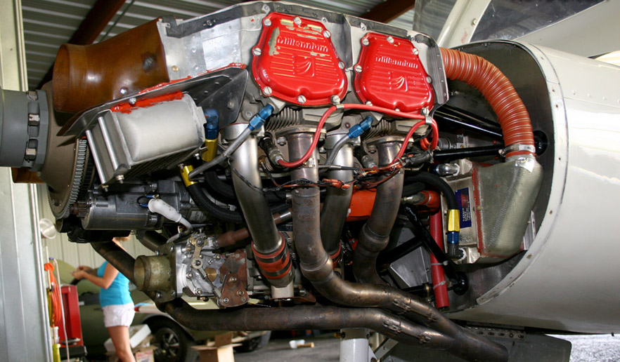
I am also bothered by my current oil cooler set-up. It works, which was a relief, but I think a dedicated inlet is better and would be even better to have it part of the outlet duct on the bottom of the cowl. I am not the best at explaining the ideas in my head, so hope this all makes sense and help answer some of your queries.