What's new
Van's Air Force

Don't miss anything! Register now for full access to the definitive RV support community.

Connecting several large guage cables to the starter?

claycookiemonster

Well Known Member
I have the 4ga cable from the aft battery coming to the starter through the firewall. From the starter I need to connect additional 4ga cables to each alternator as well as the VPX aft of the firewall.

Seems like a lot of terminals crowding onto the starter lug. There must be a way to connect a bus to that terminal which would have further terminals to handle all the other connections.

I've been searching unsuccessfully.
 
Normally, only one cable to the starter

Clay,
Did you refer to any electrical diagrams ?
Normally, only one wire/cable connects to the starter.
Here's a draft of what I planned. (Don't mind the ALT AWG#'s, they were beefed up)
 

Attachments

  • Capture d’écran, le 2020-11-07 aÌ€ 09.41.41.jpg
    Capture d’écran, le 2020-11-07 aÌ€ 09.41.41.jpg
    222.5 KB · Views: 106
Last edited:
I presume he meant ‘starter contactor’ not ‘starter’.
And those other cables can be a smaller wire/larger gauge.
 
Clay,
Did you refer to any electrical diagrams ?
Normally, only one wire/cable connects to the starter.
Here's a draft of what I planned. (Don't mind the ALT AWG#'s, they were beefed up)

You think you have a wire gauge overkill, hold my beer. :D 
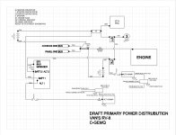
Mine are all 2ga from the 2 Odyssey PC1200 batteries in series in the rear of the plane to the starter solenoid, the alternator, and the starter, and it's a 24v system :cool:

In my defense it took forever for me to get the hang of starting my IO-540 so I could use all the help I could get and prayed nothing would overheat or melt, but now it starts normal. That starter spins that prop quite fast as it starts too.
 
Buss

Copper buss bar.
My starter contactor has one 2AWG going to the starter.
Master is connected to the starter contactor with a copper buss bar.
 
Thoughts from some guy on the Internet:

The main and vacuum pad alternators only need 6 and 10 awg respectively.

You can crimp multiple wires into one ring terminal. I made a spreadsheet: https://docs.google.com/spreadsheets/d/1RhErTJKOWOL39Aw6lWJwQCgBQZzuCNf9GmS4MCgzcnc/edit

How about picking up the VP-X along the fat wire route. The feeder to the VP-X could be 8 awg IMO. You could ask for thoughts on how to do that on the Aeroelectric List on the Matronics website. My first thought is to do something like this without cutting the fat wire: http://www.aeroelectric.com/articles/Solder_Lap_Splicing/Solder_Lap_Splices.html
.
 
I have the 4ga cable from the aft battery coming to the starter through the firewall. From the starter I need to connect additional 4ga cables to each alternator as well as the VPX aft of the firewall.

Seems like a lot of terminals crowding onto the starter lug. There must be a way to connect a bus to that terminal which would have further terminals to handle all the other connections.

I've been searching unsuccessfully.

Why do you need a 4 ga cable to each alternator and the VPX? Unless you are running some elec de-ice system, I am struggling to see the need for carrying 200 amps to these locations.
 
Clarification:
Yes, I meant the Starter Relay/Contacter. I have an aft battery, so wires to each alternator as well as the VPX will come off the starter Relay.

I was merely assuming (and we all know what that means) that wiring to those three units would need to be similar to the wiring from the battery. If I can reduce those to 8ga or similar, so much the better.

Still the question remains on how to deconflict and clean up 4 wires/cables attaching to one lug of the relay. I've seen people add a copper buss bar there to make it simpler. That's what I'm really asking about - the buss bar there to receive all the connections. Thanks.
 
I like the bulkhead connector idea because the battery to panel connection is inside and all the firewall forward connections are on another post with one pass thru. I was thinking of doing a bus bar behind the panel and passing thru a wire for the forward items off of that.

What is the consensus on sealing this bulkhead fitting and what sort of plastic is it? How does it compare to the rubber grommet passthrus in a fire?
 
Master Contactor

Clarification:
Yes, I meant the Starter Relay/Contacter. I have an aft battery, so wires to each alternator as well as the VPX will come off the starter Relay.

I was merely assuming (and we all know what that means) that wiring to those three units would need to be similar to the wiring from the battery. If I can reduce those to 8ga or similar, so much the better.

Still the question remains on how to deconflict and clean up 4 wires/cables attaching to one lug of the relay. I've seen people add a copper buss bar there to make it simpler. That's what I'm really asking about - the buss bar there to receive all the connections. Thanks.

Just to make sure. It sounds like you know.
The alternator and VPX cables should come off the Master Contactor in series with the input side of the Starter Contactor. The only cable coming off the Starter Contactor is the starter cable.

The manufacturers will have wire size on their drawings.

Are there ANL or fuses protecting the wire runs? If so, the Alternator cable connects to the ANL and the VPX connects to the second ANL.

Buss bars connects from Master to the ANL then from one ANL to the other. There may also be a Amp Shunt in the mix.
Mine is all up front so I'm not really sure how it should be done with an aft mount battery.
 
Since the starter contractor and master are (presumably) connected with a short cable between ears, why not attach 2 of the cables to the cold side of the master and 2 to the starter contractor?
 
When connecting two large electrical sources, a 60amp and a 40amp alternator to a single stud on the starter contactor via ANL fuses, is there a functional or failure mode difference between:

Concept A: Each ANL fuse gets its own connection to the starter. Total of 4 crimped terminal connectors. Two ring terminals on one stud of the starter contactor.

Concept B: The two fuse blocks are connected by a short wire with terminal rings on each end, and one fuse block is then connected to the starter contactor. Still 4 crimped terminal connections, but only one ring terminal on the starter contactor.

Concept C: A copper bus bar connects the two ANL fuse blocks and a single connection is made from the bar to the starter contactor. Only 2 crimped terminal connections and only one ring terminal on the starter contactor stud.

For extra credit: If using an uninsulated buss bar for connections like this, how is it protected or insulated to prevent inadvertent sparks or shorts?
 
<snip<>
Concept C: A copper bus bar connects the two ANL fuse blocks and a single connection is made from the bar to the starter contactor. Only 2 crimped terminal connections and only one ring terminal on the starter contactor stud.

For extra credit: If using an uninsulated buss bar for connections like this, how is it protected or insulated to prevent inadvertent sparks or shorts?

Mine is "C". Buss bars are heavily insulated with heat shrink up to the hole in the bar.
Master to Starter Contactor is a bar. #2AWG cable from Starter Contactor to the Starter.
 
Back
Top