Desert Rat
Well Known Member
I'm going breakers, not fuses or VPX and I'm getting ready to wire my breakers into the panel.
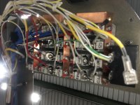
I'm going with multiple short rows right of the MFD, rather than the one row to rule them all along the bottom.
Knuckols book recommends that for a stack of short rows you should group them so that the highest amp draw is on one row which the main feed goes to, then jumper vertically to the rest. The plan is to jumper them with a vertical brass bar attached via a #8 screw to each horizontal row.
With that goal in mind, I've come up with the following plan; the first number in the fraction is the row amp capacity, and the second number is the capacity excluding transient stuff. I realize that in practice, each row will draw much less that I have listed. This is just capacity of the breakers, which seems like a reasonable way to SWAG this.
I'm planning to bring the main feed into the 3rd row down.
I've tried to scatter essential stuff out so if a jumper connection fails and kills a whole row it won't leave me blind, and also tried to group these so that stuff I might want to be able to grab and kill quickly is easy to find without looking.
Based on those parameters I'd appreciate folks reviewing my plan. If you have any suggestions or critiques I'm all ears, but the holes are already in place, so the rows are what they are.
13/10
5 ALT FLD
5 A/P
3 TRIM
50/25-ish
7.5 SDBY BATT
20 PITOT HEAT
7.5 COM2
7.5 BOOST PUMP
7.5 FLAP
27.5/22.5
7.5 STRB LGHT
FLOOD LGHT (on strobe breaker)
5 LAND LGHT
5 TAXI LGHT
5 NAV LGHT
5 CABIN LGHT
30/15
7.5 COM1
5 NAV1
5 AHRS
5 XPDR
7.5 START
14/14
3 GAD27 ACFT INTERFC
3 GEA24 ENG. MONITOR
3 AUDIO PNL
5 PFD
13/13
5 MFD
5 G5
3 ELT
SPARE
10/10
5 R. SEAT HEAT
5 L. SEAT HEAT
SPARE