What's new
Van's Air Force

Don't miss anything! Register now for full access to the definitive RV support community.

Anyone else having IC07 blowing in power module?

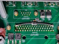
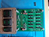
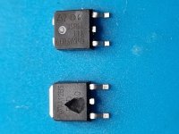
Has anyone else had trouble with mosfet IC07 in the RV12iS power module blowing? It will only be apparent if you have avionics (e.g. a NAV receiver) connected to pins 48/49 of the power module connector. If the mosfet has blown then that equipment will typically get powered even with the avionics switch in the off position.

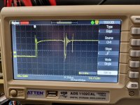
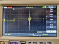
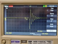
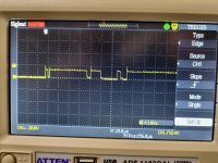
I've had it blow twice. I traced the cause to a transient on the power rail that is sometimes generated by the transponder (Dynon SV-XPNDR-261) shortly after turning the avionics switch on, in combination with a lack of any gate protection for that mosfet in the power module. I only knew the mosfet had blown because I recognised the popping sound as it failed and went looking for a blown component.
 
Its not clear to me how IC07 could ever fail due to excess current through it. Possible the xpdr is the problem.. but I'm unsure how it would generate any excess voltage when it was unpowered to begin with.

I'd look for another component nearby that is the problem. That mosfet can handle up to 35A.. surely a fuse would be blowing too.. unless it is some sort of voltage spike coming from the xpdr.. idk
 
What I believe is happening is that the excess voltage causes the gate insulation in the mosfet to fail. The mosfet gate is rated at 20V but I measured a 60V transient a short while after the avionics switch is turned on. This failure results in excess current flowing between the gate and the channel. The die heats up, causing a drain-to-source-short. Eventually the gate bonding wire fails. One of the failed mosfets has a blown-out piece of plastic in the vicinity of the gate terminal.

The transponder will generate a spike when the switch is turned off if its power input circuit has a series inductor (which it probably does have in order to prevent switching noise from its buck regulator being fed back through the power wires) and it doesn't have an input capacitor or other device to absorb the resulting back emf of the inductor.

I've posted more data on the Dynon forum, https://forum.flydynon.com/threads/...rail-blows-mosfet-in-rv12-power-module.15108/.
 
We have just had the same thing happen here with an RV12iS school project plane.

Weirdly I know of lots of Dynon equipped RV12s that have not had this happen over the years.

We can simply replace it with an FDD8880 but it will likely blow again just as you have experienced. Need some protection.

We are going to bridge a 100 ohm resistor in series to the Gate with a Zenner to ground between the resistor and the gate. Lucky I have a great electronics tech handy. :)
 
David,

Just looking for a little clarification. In one post you mentioned the problem occurred when turning on the power and then in your second post you mentioned it could happen when turning off the switch. Do you know which condition actually caused the problem?
 
I can understand it generating a voltage spike if its turned off.. same thing happens with out master relays when the magnetic field around the coil collapses.. theres ways to handle that..

But, if this were a "real" problem, I'd expect all RV12iS/Dynon planes to have blown up mosfets. I'm going to bet that Dynon/Trig changed suppliers/components inside their xpdr and this is now the result. If the RV12iS were to use relays, or simply wire the device directly to a switch, then, while the problem would still be happening..there would be fewer consequences.. and may go unnoticed. xpdr generates a spike..but who cares since it's switch is off and there's nothing else connected to the line.

So I don't think its a VANS problem.. yeah they can come up with a workaround.. but its the Dynon xpdr thats doing something it shouldn't be.. and it sounds like this a new development this year.

Reminds me of what happened to the Garmin AHARS units a couple years ago when they decided to change some internal parts and they became hyper-sensitive to "acoustic vibration".. they needed to replace a ton of units.
 
Damage on turn-off, blow-up on turn-on?

Without knowing the circuit in detail, I could imagine that the transient inductive voltage causes damage to the gate insulation while power is switched off. Since the residual energy of the collapsing magnetic field is not sufficient to finally blow up the MOSFET, this can only happen the next time it is switched on, when sufficient energy is available again.
Does this make sense?
 
But, if this were a "real" problem, I'd expect all RV12iS/Dynon planes to have blown up mosfets.

It's possible that my transponder is faulty. But if it isn't, then I think there may be two reasons why this problem hasn't been reported more widely:

1. The COM radio is powered from the same power output as the transponder. It may be that the COM radio has a capacitor across the power input of sufficient value to suppress the transient generated by the transponder. In which case, the reason I experienced this and others haven't is that I haven't yet inserted the COM radio in its tray.

2. There could indeed be many RV12s out there with blown mosfets. Unless you recognised the "pop" sound of the mosfet blowing as I did, you would only know it had blown if you connected some device to the power output on pins 48/49 of the power module 50-pin connector, and you noticed that that device was receiving power even when the avionics switch is off. The standard harness supplied by Vans for Dynon avionics does not have connections to those pins.
 
I do not know which it is, turning on or off, but it is irrelevant right now.

We have determined there is a blown transponder (can't communicate) and a blown Trig Radio....power pins now have good voltage after we repaired the board and put in a newer MOSFET and a 110ohm resistor and diode.

So two blown up bits of gear. Not impressed.
 
David,

Just looking for a little clarification. In one post you mentioned the problem occurred when turning on the power and then in your second post you mentioned it could happen when turning off the switch. Do you know which condition actually caused the problem?

I used an oscilloscope to look at what happened when the avionics switch is turned on, and what happened when it is turned off. My original theory was that turning off the avionics switch caused he transient, which caused the mosfet to develop a gate-to-channel short, then turning it on again caused that short to blow the mosfet. But I found there wasn't a significant transient when I turned the avionics switch off. OTOH there was sometimes a transient of up to +/-60V shortly after turning it on and it was clear that this was related to contact bounce in the switch.

I speculate that the reason that I observed this after turning the switch on and not when turning the switch off is to do with the load on the switching regulator in the transponder. Shortly after the transponder is powered up, it will need to charge the output capacitors of that regulator. If the regulator doesn't have a good soft-start function built in, that will result in it drawing a large current that may be sufficient for any input inductor to generate a large spike when the source of that current is removed due to the switch contacts bouncing open. Once those capacitors are charged, and with the transponder in standby so that it is not transmitting, the current drawn from the power input will be much lower; hence a much smaller transient when the power is turned off.

It's also possible that the switching regulator has marginal stability. When an L-C input filter is added to a switching regulator to reduce EMI transmitted out of the power rails, it tends to make the regulator unstable because of the negative input slope resistance of the regulator (i.e. when the input voltage goes up, the current it draws goes down). This is normally managed by adding an extra capacitor with carefully-chosen ESR at the regulator input. The degree of instability varies with load and output voltage. It may be that contact bounce sometimes removes power when the regulator is operating under the conditions in which it is least stable.

I've attached some oscilloscope traces. The first shows the moment the switch is turned on, some contact bounce and the transient. This is one of the largest I measured; it's usually smaller than this. The second is a close-up of the same trace. The third is a typical trace when the transponder is not connected, showing contact bounce but no transient.,
 

Attachments

  • 2023-12-09 18.46.32.jpg
    2023-12-09 18.46.32.jpg
    373.1 KB · Views: 12
  • 2023-12-09 18.46.46.jpg
    2023-12-09 18.46.46.jpg
    417.9 KB · Views: 9
  • 2023-12-09 18.43.04.jpg
    2023-12-09 18.43.04.jpg
    427.6 KB · Views: 5
I do not know which it is, turning on or off, but it is irrelevant right now.

We have determined there is a blown transponder (can't communicate) and a blown Trig Radio....power pins now have good voltage after we repaired the board and put in a newer MOSFET and a 110ohm resistor and diode.

So two blown up bits of gear. Not impressed.

I'm sorry to hear that your kit has failed. I have wondered whether connecting the COM radio would suppress the transient sufficiently to avoid the mosfet blowing, but I didn't want to try it in case the transient damaged the COM radio. Your experience suggests I was wise not to try it.

I intend to add a TVS diode across that power rail, either in the transponder wiring loom or on the power module - or possibly both. The TVS diodes I plan to use for this are https://uk.rs-online.com/web/p/tvs-diodes/7103430 (a surface mount device that could probably be fitted on top of the 10K mosfet gate resistor) and/or https://uk.rs-online.com/web/p/tvs-diodes/6365555 (a wire-ended device that could be fitted either in the wiring loom or across the pins of the 50-way connector in the power module). These have a minimum breakdown voltage of 16.7V, which should be sufficiently greater than the maximum battery voltage of 14.6V to be safe. In the unlikely event of a sustained aircraft bus voltage significantly greater than 16.7V, the fuse feeding the avionics switch will blow but the EFIS will continue to receive power.
 
It's possible that my transponder is faulty. But if it isn't, then I think there may be two reasons why this problem hasn't been reported more widely:

1. The COM radio is powered from the same power output as the transponder. It may be that the COM radio has a capacitor across the power input of sufficient value to suppress the transient generated by the transponder. In which case, the reason I experienced this and others haven't is that I haven't yet inserted the COM radio in its tray.
Not only is the COM radio likely to add additional capacitance to the 12 volt bus, but it's also very likely to include some transient protection on its input. While designed to protect itself (and not the 12 volt bus), often this protection will include elements that absorb some of the energy from transient events. And by absorbing some of that energy, it ultimately decreases the magnitude of transient events for everything on the bus.

2. There could indeed be many RV12s out there with blown mosfets. Unless you recognised the "pop" sound of the mosfet blowing as I did, you would only know it had blown if you connected some device to the power output on pins 48/49 of the power module 50-pin connector, and you noticed that that device was receiving power even when the avionics switch is off. The standard harness supplied by Vans for Dynon avionics does not have connections to those pins.
The standard Garmin VFR harness doesn't have anything connected to these pins either. However, the Garmin IFR harness does. If this was a common failure (among Dynon and Garmin systems) we would see more people reporting this problem.

Looking at the captured waverform, we have a peak of around 60 volts that lasts for about 2 microseconds. At least in the automotive world, the captured waveform isn't anything to be concerned about. These types of transients (and worse) are expected on a 12 volt bus.

Does anyone have a picture of the front side of this PCB? I'd like to take a closer look at it. If there isn't any protection for the FET and you're actually seeing 60 volt transients on a 20 volt rated gate, that's likely sufficient to burn a hole in the gate oxide and destroy the FET.
 
Here's a photo of the front side of the PCB including the mosfets concerned after I replaced them for the second time. There is no gate protection as can be seen from the schematic on page 8 of https://www.vansaircraft.com/wp-content/uploads/2022/10/WH-00133-1.pdf. Also a photo of the first two mosfets I replaced. The N-channel mosfet has a piece of plastic blown out and a source-to-drain short. The P-channel mosfet that it drives may be OK but I replaced it as a precaution, because it's likely to have experienced excessive gate-to-source voltage too.

The Garmin transponder likely doesn't generate this type of transient, which would explain why this issue isn't seen when using Garmin IFR avionics.
 

Attachments

  • 2023-12-13 16.59.01.jpg
    2023-12-13 16.59.01.jpg
    315 KB · Views: 37
  • 2023-12-13 16.59.53.jpg
    2023-12-13 16.59.53.jpg
    287.8 KB · Views: 27
Last edited:
STOP PRESS

So more to learn today :(

I bench tested the Trig radio and it powers up, so it appears there is some other issue on the board. We tested 13.2v at the pins to the radio and transponder, but it appears there may be voltage but no load capacity perhaps. Perhaps the Transponder is fine also. We just need a stable power module.

Ray our friendly radio tech will be back on the job today. Poor fella!

Personally, this is why I hate bespoke custom wizardry when simple C/B's and busbar work just fine. Having done many installs across VPX, AFS-ACM and C/B systems, including all ROTAX, Continental & Lycoming variants the RV12 system is plane and simple dumb. It is a solution to a problem that did not exist. Don't bother debating it. It is a fact.

Hopefully no SteinAir wiring stuff ups like the last RV12 :(

Onwards and upwards. :)
 
Interesting comment, David. Makes me grateful that the builder of my 12 installed a busbar and CBs. Nice to fly behind rows of CBs and simple switches.
He was a sparkie by trade and had previously built a 6 and a 7. Obviously learnt something along the way.

Jack
 
Yes Jack.......I will say that like all things when they work, they work fine. The big BUT here is that the vast majority of A&P's and builders will struggle fault finding.
 
STOP PRESS II

We determined the radio had not racked fully. Too many things in and out late yesterday. Fresh attack this morning has revealed the radio and transponder are working fine.


BUT......fuel pumps do not. It has the latest version HIC controller and the wiring is 100% correct to the new connector (checked 4 times) as per the Service Letter. Anyone had that drama?
 
STOP PRESS II

BUT......fuel pumps do not. It has the latest version HIC controller and the wiring is 100% correct to the new connector (checked 4 times) as per the Service Letter. Anyone had that drama?

What color is the HIC LED light? Problem could be a fuse or relay that is not seated inside the Rotax fusebox, or wiring between the HIC module and the ignition module. Or, dare I even say it, the wires to the fuel pump of connectors in the center channel aren't connected :)

I have access to a Dynon xpdr if you think throwing my oscilliscope on it would gather any useful information. Its installed in an RV7 still under construction.. and i believe on its own circuit supplied by a VP-X.
 
Bright white colour. What are the codes?

Seems our MOSFET and resistor/diode protection has worked a treat. Happy with that now. :)
 
Bright white colour. What are the codes

From the wiring diagram:
Code:
Diagnostic LED Color Codes when Installed in Aircraft
==================================
EXPECTED PRE-START CONDITION
SBB & FSP & Batt Bus Power (all high) = WHITE
----------------------------------
EXPECTED POST-START CONDITION - After ~60 seconds with Engine Running & SBB "Start Computer" Timed Out
FSP & Batt Bus Power (no SBB) = YELLOW
~~~~~~~~~~~~~~~~~~~~~~~~~~~~~~~~~
POSSIBLE PRE-START FAULT COLOR CODES
FSP Only (no SBB & no Batt Bus Power) = Red
SBB Only (no FSP & no Batt Bus Power) = Blue
Batt Bus Power Only (no SBB & no FSP) = Green
FSP & Batt Bus Power Only (no SBB) = Yellow
SBB & Batt Bus Power (no FSP) = Teal
FSP + SBB (no Batt Bus Power) = Magenta
*********************************
Batt Bus Power = +12v from X3 Connector Pin3
FSP = Fused Start Power, +12v from DB25 Pin 6 & 7
SBB = Start Button Bypass, +5v from DB25 Pin 3
 
Last edited:
That's handy info 12is ;)

The good news is we have debugged all the issues so far. There could be more.

It really bothers me that we find too many OEM wiring errors. The number of "wiring shop" errors from the supplier who we all know, in my experience is at least a couple per system now. And not hundreds but 100% of several. It should not be that way. Maybe I only get called when the SHTF. :rolleyes:

Thanks everyone who helped and to others be very aware of what has been going on here.
 
Interesting comment, David. Makes me grateful that the builder of my 12 installed a busbar and CBs. Nice to fly behind rows of CBs and simple switches.
He was a sparkie by trade and had previously built a 6 and a 7. Obviously learnt something along the way.

Jack

I agree, I think CBs are far better than fuses, especially pullable ones for critical functions such as autopilots.

I don't know why Vans used mosfets to switch the secondary COM/NAV power output. They obviously wanted to fuse it separately; but surely using a double-pole switch (one for each circuit) would have been simpler than a single pole switch and mosfets?

Another reason not to use mosfets to switch power outputs is that if you get a large overload (e.g. a short circuit), the mosfet will blow before the fuse does.
 
STOP PRESS II
BUT......fuel pumps do not. It has the latest version HIC controller and the wiring is 100% correct to the new connector (checked 4 times) as per the Service Letter. Anyone had that drama?

Have you checked that part of the wiring in the harness? My harness had the red/black wires for one of the fuel pumps connected to the wrong pins of the fuel pump connector. See photo - the red and black wires should not go to different pins on the two fuel pump connectors.
 

Attachments

  • 2023-12-15 15.05.13.jpg
    2023-12-15 15.05.13.jpg
    152.4 KB · Views: 12
I was hoping the schematic in the wiring diagram was simply representative of what was on the PCB. That there were things like transient protection, and bypass capacitors for the voltage regulator installed, but just not shown...

For those that add a LEMO (or other powered) connector for your headset, one other source I see for IC07 damage is ESD. There is a power line that goes directly from something the user interacts with, to the gate on the MOSFET (with no protection). If there was an ESD discharge (to the headset power line) as someone was plugging their headset in, this could definitely takeout IC07.
 
Good point about the LEMO headset socket being a potential source of ESD.

I've installed a 15V 500W peak TVS diode across the COM power output. Anode to pins 1-2 of the 50-way connector, cathode to pins 16-17. Part number is SA15A-E3/54. After taking the photo I secured it to the PCB using hot melt glue. Then I reinstalled everything and scoped that power rail again. There is still ringing on the rail when the transponder is connected and the switch contacts bounce, but the previous transient is almost entirely eliminated. Note the vertical scale in my photo is 5V/division this time instead of 20V/division.
 

Attachments

  • 2023-12-16 14.59.25.jpg
    2023-12-16 14.59.25.jpg
    358.6 KB · Views: 24
  • 2023-12-16 18.33.14.jpg
    2023-12-16 18.33.14.jpg
    406.9 KB · Views: 19
Have you checked that part of the wiring in the harness? My harness had the red/black wires for one of the fuel pumps connected to the wrong pins of the fuel pump connector. See photo - the red and black wires should not go to different pins on the two fuel pump connectors.

The fuel pump not running and so on was eventually solved by checking the connection on the Vans SB for the new control board.

The wiring change over had two of the wires marked wrong. So without misleading anyone to just check the two we had, check all of them. We had two that had each others other end labeled, i.e. 1234-6789 and 6789-1234 instead of 1234-1234 & 6789-6789.

Not sure who made these kits up, but it would not surprise me if it was the harness manufacturer :(

https://www.vansaircraft.com/wp-content/uploads/2022/10/SB-00058-RV-12iS-HIC-Module-Replacement.pdf
 
Back
Top