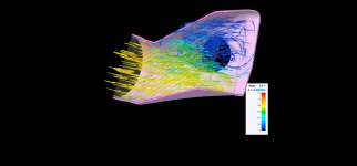
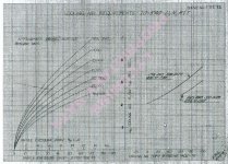
I've done some math and calculated the mass flow at the end of the air duct, and it is roughly 12-13 lbs per second based on the simulation if the airflow was constant throughout the entire cross section of the inlet; which it is not.
You have a 5" ring. Area is 19.625 sq in, or 0.13628 sq ft
Velocity (from your first post) is 160mph or 235 ft per second.
0.13628 x 235 = 32 cubic feet
Standard density at 2000 feet is 0.072 lbs per cubic foot.
So, 32 x 0.072 = 2.3 lbs per second for one inlet.
2 inlets = 4.6 lbs
if there is no throttling downstream of the inlets. That would include flow restriction due to separation.
Either go low Vi/Vo, or do whatever it takes to go high Vi/Vo without separation...meaning a good internal diffuser. That's not the one with the ramp, and I don't think it can be done
well without a propshaft extension.
But the Vi/Vo ratio would still not be good(?)
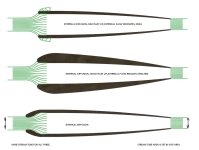
There is no good or bad Vi/Vo. The ratio of inlet velocity to freestream velocity merely indicates where the cooling flow is being slowed, either externally, out in front of the inlet (low Vi/Vo) or internally, after the air has passed through the inlet (high Vi/Vo). Properly designed, either works fine.
Dave Anders recently wrote a nice article focusing on high Vi/Vo design, although he didn't actually use the term. It's arguably the superior approach in terms of least
external drag for a high and fast airplane in cruise. Get everything just right and there can't be any external separation around the inlets. But the internal diffuser shape can be critical.
A low Vi/Vo inlet
must re-direct some of the freestream around the outside of the cowl, and if the inlet lip and cowl just aft of it are poorly shaped, it separates externally, just like your bad internal separation. However it need not do so in any significant degree. Take a look at the early NACA papers on radial cowl development. You'll find pressure plots, and see which leading edge shapes tended to separate. Classic radial cowls are just big examples of a low Vi/Vo inlet.
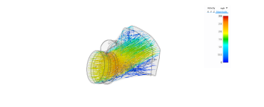
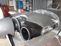
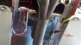
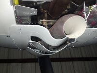
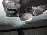
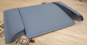
Aside from moving the inlet vents up, what are some design ideas to help mitigate the turbulence and high velocity at the outlet portion? I'll change all of the abrupt angles as much as possible, but the alignment is still poor.
It's a classic losing battle...pick a short cowl and plenum lid, and then try to couple them together as an afterthought. It's a better approach if a builder picks high or low Vi/Vo, and then optimizes the entire system to suit the choice.
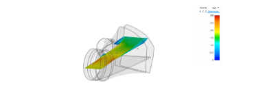
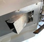
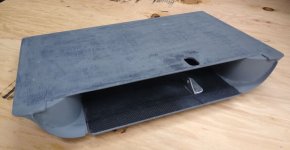
Putting a ramp in the bottom of the inlet influenced the directional issue, but comes at a price of keeping velocity high....
...which is a heck of a lot better than losing the energy into turbulence. The energy is still in the airstream as velocity. It going to hit the fins and back wall, and slow in that way, raising pressure. It will work (lots of RV installs are doing precisely that), but it's not super efficient. For example, lots of lost energy in plain 'ole surface friction in the high velocity duct.
BTW, as my mentor liked to point out, low Vi/Vo diffusion is frictionless.