
Van's Air Force
You are using an out of date browser. It may not display this or other websites correctly.
You should upgrade or use an alternative browser.
You should upgrade or use an alternative browser.
4-1 exhaust/cowling remedies
- Thread starter Freemasm
- Start date


Do I recall correctly, a Rocket has an exit ramp inset into the belly, like the -8?
I built four different cowl panels, each progressively smaller in exit area, all around a 4-into-1. The fourth included variable area. It's just glass. Build what you need.
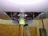
Stock, never flown. I did send the pipes back to AWI with instructions for shortening the headpipes just a little. That raised the whole pipe set straight up. Compare the pipe in the first two photos below:

#1, before first flight:

First three exit panels:

Raw panel #4, prior to cutting the variable exit door:

#4, early on, pressure and temperature measurements underway. Still flying it, about 1000 hours now.


I built four different cowl panels, each progressively smaller in exit area, all around a 4-into-1. The fourth included variable area. It's just glass. Build what you need.
Stock, never flown. I did send the pipes back to AWI with instructions for shortening the headpipes just a little. That raised the whole pipe set straight up. Compare the pipe in the first two photos below:
#1, before first flight:
First three exit panels:
Raw panel #4, prior to cutting the variable exit door:
#4, early on, pressure and temperature measurements underway. Still flying it, about 1000 hours now.
Attachments
Last edited:
Freemasm
Well Known Member
Uggg. Unfortunately No.Do I recall correctly, a Rocket has an exit ramp inset into the belly, like the -8?
I built four different cowl panels, each progressively smaller in exit area, all around a 4-into-1. The fourth included variable area. It's just glass. Build what you need.
Stock, never flown. I did send the pipes back to AWI with instructions for shortening the headpipes just a little. That raised the whole pipe set straight up. Compare the pipe in the first two photos below:
View attachment 66184
#1, before first flight:
View attachment 66179
First three exit panels:
View attachment 66178
Raw panel #4, prior to cutting the variable exit door:
View attachment 66181
#4, early on, pressure and temperature measurements underway. Still flying it, about 1000 hours now.
View attachment 66182
View attachment 66183
A ramp would certainly have helped things. The bottom of the FW is straight. There is a fairly even gap of ~2" between the cowling and the bottom of the FW along the interface. It appears to have been designed for the Vetterman 4 pipe exhaust. I was talked out of that. Different story.
The cowl is tight. Nothing can fit between the bottom of the sump (Superior Cold Air) and the cowl. The tail pipe has to be very tight with the bottom of the FW/Fuse. Mod'ing the cowl around the tailpipe is the easy part. There is less than 1/2" between the bottom exhausts and the cowl at the forward most part (where the pipes level out). The "two wide" portion continues to drop into the cowling space. That interference is both deep and wide.
I have over $2300 into this exhaust after having to get Clint (see below) to extensively mod the #1 and #3 downcomers to facilitate over 1.5" of interference at the "elbows". There's still zero gap at the edges of the airbox.
Trying to see what others have done or if I should punt this POS. There were/is several quality issues with the AWI fab, a bit of a surprise. They had no desire to help mod it to make it work.
@dan. Got any profile pix from the side for the area of interest?
Anybody else live through this? Would really appreciate your knowledge/experience. Thx
Freemasm
Well Known Member
No pix there as I was looking for advice from people who had lived this. I'll add some below (over time) off of the phone as I can find them

Cowl is tight

Original I/F at downcomer 3

Original I/F at downcomer 1

Max cowl vert position with hard interference

Original routing bottom side

Left RIght side after mod by Clint at Vetterman's. AWI had no interest in helping solve

Right Left side after Clint Mod. Ref # 1 downcomer routing
Cowl is tight
Original I/F at downcomer 3
Original I/F at downcomer 1
Max cowl vert position with hard interference
Original routing bottom side
Attachments
Last edited:
Freemasm
Well Known Member

No tunnel

Yet another quailty issue

After Vetterman rework.
Interference with bottom cowl begins just after straight sections. Increases to over an inch of I/F towards the firewall.

Still slight cowl contact . Note proximity to engine (solvable).

Basically same here.
Anyway. I can probably solve the front side I/F by throwing even more money at this. What did the earlier adopters do for the manifold and tail pipe sections? Please respond before I take a chainsaw to this thing.

Quality issues. Note different lengths for strap lugs.
Last edited:
No pix there as I was looking for advice from people who had lived this.
Yeah, but you never can tell what we might both learn. For example, it appears AWI changed the design.
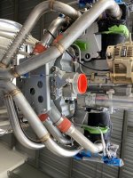
Your pipe routes the front cylinders to the bottom of the collector:

Mine, delivered circa 2008, runs the front cylinders to the top of the collector...

...which eases clearance in the forward part of the lower cowl:

I can only speculate as to why they changed it. My guess would be to provide more clearance for the ever-popular "cold air" intakes.
I'm curious. Did AWI say this pipe would fit a Rocket cowl? And do they only make this version?
Toobuilder
Well Known Member
I have rebuillt the lower cowl on my Rocket a half dozen times to accommodate exhaust and induction bits. Latest version drops the lower OML by 2 inches to make room for a pair of 5 inch diameter augmentor tubes. looks like you just need a few blisters to clear some tight places. Glass work is a bunch easier and cheaper than a new exhaust.

vfrazier
Well Known Member

Another builder, Al Mullenbach, modified his lower cowling to fit his 6 into 1 exhaust. I believe that he made a mold and could possibly make a lower portion, or maybe an entire lower cowl, for you.
I have the same 4 into 1 exhaust that you have. I can't wait to see if it is as much fun as you've had.
Toobuilder
Well Known Member
It's just fiberglass... Cut a hole. Make blister.


Virtually half of my cowl is made of .250” foam board from recycled office calendars or card stock from recycled manilla folders. Compared to this (which was pretty easy), cutting a few football shaped ellipses around your tight spots and then adding a blister with a few layers of glass would be a piece of cake. This is a one weekend (likely one day) job, tops.
Virtually half of my cowl is made of .250” foam board from recycled office calendars or card stock from recycled manilla folders. Compared to this (which was pretty easy), cutting a few football shaped ellipses around your tight spots and then adding a blister with a few layers of glass would be a piece of cake. This is a one weekend (likely one day) job, tops.
Last edited:
Toobuilder
Well Known Member
An easy way to make a form fitting blister for situations like the OP has is to identify those areas that are too close to the pipes with a sharpie. Mark all areas that are within, say, an inch in all directions. Cut out this area of the cowl in a smooth ellipse. Do it right and the opening should be centered on the offending section of pipe. Remove the cowl. Go grab a piece of 1 inch thick foam rubber and some release plastic that’s a bit larger than the hole, and tape it in place over the hole on the engine side, plastic out. Reinstall the cowl, and the pipe will displace the foam and plastic out into a pleasing aerodynamic blister. Glass directly over this “form” with 2 layers of 6 oz cloth. When it cures, remove the cowl and peel away the foam and plastic. With a sander, Work the inside of the blister just enough to knock the shine off and smooth the transition between the base cowl and the blister. Cut 2 pieces of 6 oz glass in an ellipse shape 1 inch and 2 inches larger than the original cut out. Place the smaller patch into place, smooth out all wrinkles, and wet it out with resin. Repeat with the larger piece. Once cured, prep the outside as required for paint.

