That will need to be addressed but thinking more about the cut out,...my engine is essentially a zero time engine and has a solid crank. I won't be swapping it out for a constant speed prop. Since the mod will not solve my issue of the fuel pump conflict, probably not a worthwhile mod, for me. Any other reasons to do it?
How do I know what oil cooler to buy? I see they are rated by "rows".
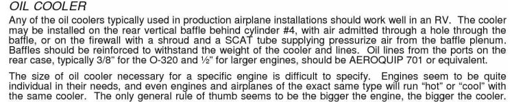
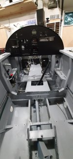
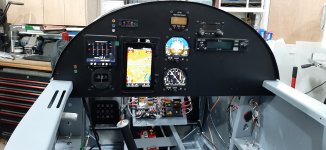
 Although not my favourite instrument layout now, the aluminum work turned out ok. And it was an interesting project. For anyone using an EDM350, the diameter of the case is actually around 3.000" so a regular instrument hole is sloppy. The mod allowed me to make the hole a better fit anyways.
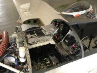
 I own a 94 -4 that I completely refurbed and modernized. My interior was painted that same hideous blue, It kept me up at night…I was never so happy when I repainted it. Used a flat gray epoxy primer, turned out great and is very durable. My apologies in advance if you are partial to the blue.
. It seems #4 is common from what I could find on line.I would at least place the fuse blocks in a position where you can get at them to change a fuse Without removing the top skin. Maybe up side down on the bottom of the shelf so you can at least reach under the panel to get at them.To wrap up some of the previous posts....
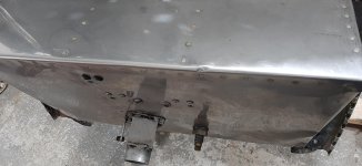
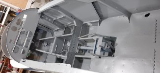
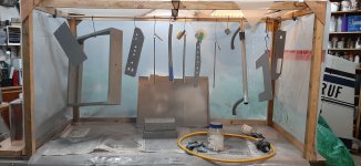
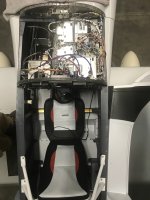
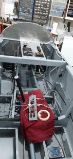
Static ports are done
Rudder pedals are reinstalled (waiting on a few pieces of hardware )
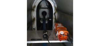
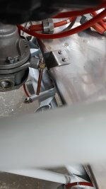
Master brake cylinder is plumbed on inlet side. I replaced the plastic plumbing fittings with some hydraulic fittings. When the shop made my lines up, they put those fittings on so I had to change over. I like them much better though. You can see them in one of the photos. Local shop so nice.
I assembled the FlyLED's control module for the Strobe/Nav lights. I will give them a kudos. Nice PC board to work with. Well documented kit. Good support.
I decided to take the advice and sentiment expressed in previous posts and ditched the little rocker switches for more robust toggle switches. Thanks for the input there.
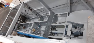
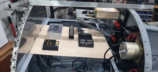
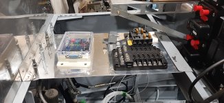
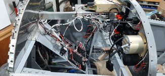
I am starting to work on the wiring. I will be putting a shelf behind the instrument panel to support the fuse blocks, grounding blocks, light control module, etc. I looked at options like on the floor for the control module, firewall for the fuse blocks, etc. but I like the shelf, and it be will be nice to install and for maintenance.
But, thinking about the wiring, how does one make the actual physical connections for the communications pins? I don't have much to connect, but the engine monitor can connect to the GPS RS232 lines to calculate fuel necessary, and the AV30's connect to the GPS for course information. The pins don't look large enough to put two wires into them. I think my system is too simple for the junction boxes I see in larger systems. So is it a matter of stripping the wire back from the pin and joining it there? I think Stein calls it "window stripping"? That is about the best video that I have found but hoping someone can confirm this is what I need to do for the communications lines. Or do I use a terminal block outside of any connector? I would be concerned about losing shielding but maybe those lines are not sensitive to interference? Any suggestions?
Well, I, for one would not put it under the top forward skin. There are a TON of screws that would have to be removed every time you had a fuse issue. PITA. Looks like there is plenty of room under your starboard switch panel. That said, in all the flying I have done, I have never had to rest a breaker. I would still think about putting it in a more accessible place. If you do blow a fuse, you know it's going to be somewhere that isn't near your home base. There you are, out on the ramp in the rain.........I have been toying with this, as well as putting the shelf on a hinge of some sort. But my reasoning for it being as shown is that, at 60 years of age, I would rather undo the screws and lift the cover off than contort myself under the panel and work upside down. Not sure if I will regret this or not. Depends on how many times I have to take the skin off or not.
Just a thought.Well, I, for one would not put it under the top forward skin. There are a TON of screws that would have to be removed every time you had a fuse issue. PITA. Looks like there is plenty of room under your starboard switch panel. That said, in all the flying I have done, I have never had to rest a breaker. I would still think about putting it in a more accessible place. If you do blow a fuse, you know it's going to be somewhere that isn't near your home base. There you are, out on the ramp in the rain.........
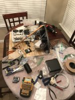
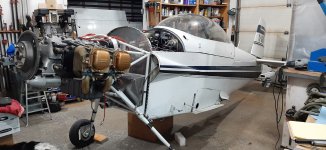
Your airplane is looking MUCH better than the pictures you posted after you acquired her.....Keep up the good work!
I have been toying with this, as well as putting the shelf on a hinge of some sort. But my reasoning for it being as shown is that, at 60 years of age, I would rather undo the screws and lift the cover off than contort myself under the panel and work upside down. Not sure if I will regret this or not. Depends on how many times I have to take the skin off or not.
I placed mine on the front of the electronics tray angled down. It’s easy to reach under the panel and change them by feel. I keep a diagram of which fuse is in each slot so I can remember which is which.Well, I, for one would not put it under the top forward skin. There are a TON of screws that would have to be removed every time you had a fuse issue. PITA. Looks like there is plenty of room under your starboard switch panel. That said, in all the flying I have done, I have never had to rest a breaker. I would still think about putting it in a more accessible place. If you do blow a fuse, you know it's going to be somewhere that isn't near your home base. There you are, out on the ramp in the rain.........
Your airplane is looking MUCH better than the pictures you posted after you acquired her.....Keep up the good work!

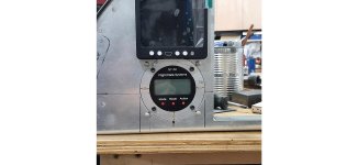
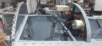
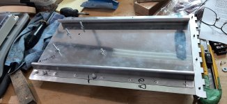
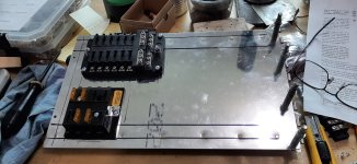
I decided to consolidate suggestions with my initial thoughts. I made the shelf that swings down with just 2 screws, should I need/want to get at the panel via the pilot seat. Or access it from the top which will make initial wiring much easier. Removing the hinge pin also allows me to slide it left or right for maintenance issues, but the pedals and brake components are pretty accessible without moving it anyways.
Thanks for the input!
Thought the same... 2 stiffening angles, or other idea, will help. Still, I like that hinge idea, wish my whole panel was hinged...concerns about vibration
I didn't use pluggable connectors in the wing roots for the flyleds and instead ran the wiring from the wings into the fuselage to be spliced under the seat floor. Once the wings are on there is no intention to ever remove them and if becomes necessary to do so then the lighting wires would just be cut.I have been moving along with the wiring. Which prompts a question....
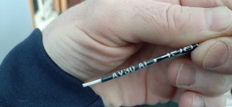
The wiring to the strobes in the wings is a shielded wire. To make the connections at the wing roots and maintain the shielding, what connectors are you all using? The DB series? I have some DB15's coming from Steinair that I ordered on speculation so that does work out well. Or does a slight break in the shielding for the purpose of a connection not cause an issue? It will be continued through the connector (Molex maybe?) to the wing wiring. Wings won't be going on for a while, so I have time, but I would rather have connectors in place before I head to the airport. Suggestions? FlyLED's lights.
Thanks
If it hasn't been said already, label ALL your wires, both at the beginning and the end. It will make things MUCH easier when trying to chase down an electrical problem!Thanks Paul. I would rather not be doing those connections to the controller board at the airport, but you make good points. I don't ever plan on pulling the wings again, and if I do, the wing lighting wires will be a small concern.
Panel wiring (or rather, general wiring) is moving along. But moving, so that is a good thing....
Hi ShawnThanks Paul. I would rather not be doing those connections to the controller board at the airport, but you make good points. I don't ever plan on pulling the wings again, and if I do, the wing lighting wires will be a small concern.
Panel wiring (or rather, general wiring) is moving along. But moving, so that is a good thing....
If it hasn't been said already, label ALL your wires, both at the beginning and the end
Hi Shawn
The location of your flyleds controller presents another option, which is to use a crimp Dsub connector at the controller instead of the solder connector that comes in the kit. The wires in the wings would be made long enough and with a service loop so as to reach the controller. The wires can be terminated with the crimped-on pins before going to the airport. At the airport the remaining step would be to push the pins into the Dsub connector.
) 
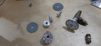
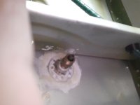
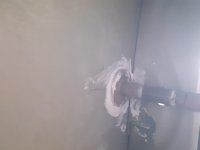
Any amount of threads beyond the nutplate are just along for the ride. 1 thread past gives you assurance of 100% engagement. Is your hinge line correct, or is the rudder/ vertical fin too far apart? I'd take a look at it all. As long as it's able to have a functional jam nut and 1 thread you should be fine.I noticed today that the rod bearings that form the hinge for the rudder do not appear to go as far into the nutplate as I would like. Does anyone know the thread length on this part?
BEARING MD3614M
store.vansaircraft.com
The specs give the diameter but not the thread length. The drawing (30-4) shows several threads showing past the nut plate, as would be expected. Perhaps if the rod end gets bottomed out, I might have enough threads. As I type, maybe that will be the resolve. I see on a thread regarding a 14? I think ...that someone mentions a longer version of that rod end. My plans do not comment on this. Anyone recall issues in this area?