

Garmin GNS 430 Memory Battery Replacement
About a month ago a "Memory Battery Low" message was displayed on my Garmin 430. I read a few posts online about replacing the battery at home rather than sending the unit to Garmin along with hundreds or usually thousands of $$$, and I read that if you choose to not upgrade to WAAS, Garmin will remove your serial number tag. I worked in the electronics industry and have a lot of experience replacing circuit board components, and would not recommend this battery replacement to anyone not knowledgeable with ESD precautions and the proper use of a soldering iron, solder sucker, and solder wick. It will be a very expensive mistake if you damage the circuit board. The battery location on the GNS 530 circuit board looks the same as the 430.
If you are up to the task and have the proper equipment and experience, then there are really no surprises. First of all you will need a CR 14250SE-FT, a 3 volt lithium memory battery with 3 solder pins. They presently sell online for $13.75 including shipping. The battery will deliver 3+ volts until it reaches a minimum voltage of about 2.50v and then it triggers the "Memory Battery Low" message. The new battery voltage measured 3.20v and the removed battery measured 2.53v. The product data sheet mentions that a low internal resistance gives the battery a shelf life of about 10 years and a work life of about 5-7 years.
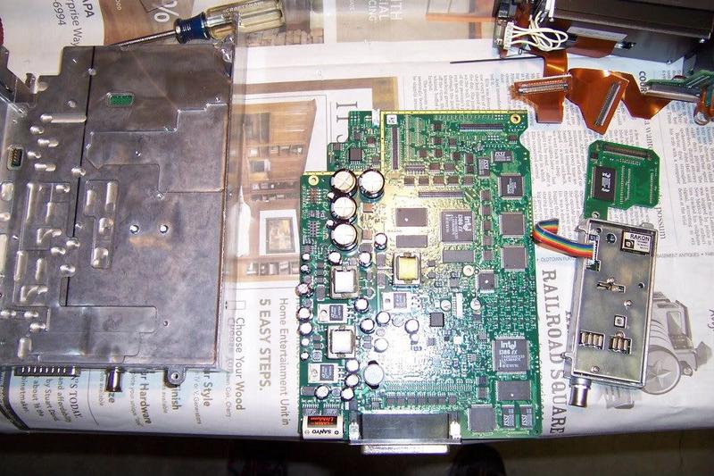
As with any circuit board rework, take all ESD precautions. Remove top cover and the bottom case screws, the bottom case has one hinge and folds open. The battery is now visible on the lower left corner of the main circuit board in the photo. There are 2 Intel 386ex CPU's embedded on the board which provide the necessary computing power and are very susceptible to ESD damage. Remove the screws that hold the front panel in place. Remove all the electrical connectors and all the circuit board screws, including the power transistor screws attached to the main board. Remove the microcircuit package and circuit board attached to the top of the main board. Be careful, most of the electrical connectors are loaded with very delicate pins. Remove 2 rear connector screws. Remove the main board by lifting up away from the case, and leave the insulator sheet in place. Now you have the main board in hand and are able to de-solder the battery. Use a solder sucker and solder wick to remove the solder from the three battery pins, and remove the adhesive that holds the battery in place. Replace the battery and solder the new battery leads in place. This is a multilayer circuit board and you have to be sure the solder remains liquid long enough so it wets all the layers and forms a good wet fillet on both sides of the circuit board. Place a large dab of RTV between the battery and circuit board to prevent the solder leads from fracturing due to vibration. Let it sit for a day for the RTV to outgas and cure, this will give you some time to take a few photos and admire your handiwork.
Now follow the sequence back and be sure to give the proper respect to all the fragile connector pins. Use a thread locker on all the screws. Mount the 430 back into the panel and power it up. It will take about 5 minutes to acquire enough satellites to load the current almanac and orbital data required to display and record your current GPS location. All memory data stored in RAM including way points and flight plans will be lost after battery replacement, and will need to be re-entered. As a precaution before you start, take a photo or make a copy all your configuration settings in case they ever need to be reset.
About a month ago a "Memory Battery Low" message was displayed on my Garmin 430. I read a few posts online about replacing the battery at home rather than sending the unit to Garmin along with hundreds or usually thousands of $$$, and I read that if you choose to not upgrade to WAAS, Garmin will remove your serial number tag. I worked in the electronics industry and have a lot of experience replacing circuit board components, and would not recommend this battery replacement to anyone not knowledgeable with ESD precautions and the proper use of a soldering iron, solder sucker, and solder wick. It will be a very expensive mistake if you damage the circuit board. The battery location on the GNS 530 circuit board looks the same as the 430.
If you are up to the task and have the proper equipment and experience, then there are really no surprises. First of all you will need a CR 14250SE-FT, a 3 volt lithium memory battery with 3 solder pins. They presently sell online for $13.75 including shipping. The battery will deliver 3+ volts until it reaches a minimum voltage of about 2.50v and then it triggers the "Memory Battery Low" message. The new battery voltage measured 3.20v and the removed battery measured 2.53v. The product data sheet mentions that a low internal resistance gives the battery a shelf life of about 10 years and a work life of about 5-7 years.
As with any circuit board rework, take all ESD precautions. Remove top cover and the bottom case screws, the bottom case has one hinge and folds open. The battery is now visible on the lower left corner of the main circuit board in the photo. There are 2 Intel 386ex CPU's embedded on the board which provide the necessary computing power and are very susceptible to ESD damage. Remove the screws that hold the front panel in place. Remove all the electrical connectors and all the circuit board screws, including the power transistor screws attached to the main board. Remove the microcircuit package and circuit board attached to the top of the main board. Be careful, most of the electrical connectors are loaded with very delicate pins. Remove 2 rear connector screws. Remove the main board by lifting up away from the case, and leave the insulator sheet in place. Now you have the main board in hand and are able to de-solder the battery. Use a solder sucker and solder wick to remove the solder from the three battery pins, and remove the adhesive that holds the battery in place. Replace the battery and solder the new battery leads in place. This is a multilayer circuit board and you have to be sure the solder remains liquid long enough so it wets all the layers and forms a good wet fillet on both sides of the circuit board. Place a large dab of RTV between the battery and circuit board to prevent the solder leads from fracturing due to vibration. Let it sit for a day for the RTV to outgas and cure, this will give you some time to take a few photos and admire your handiwork.
Now follow the sequence back and be sure to give the proper respect to all the fragile connector pins. Use a thread locker on all the screws. Mount the 430 back into the panel and power it up. It will take about 5 minutes to acquire enough satellites to load the current almanac and orbital data required to display and record your current GPS location. All memory data stored in RAM including way points and flight plans will be lost after battery replacement, and will need to be re-entered. As a precaution before you start, take a photo or make a copy all your configuration settings in case they ever need to be reset.
Last edited:

