What's new
Van's Air Force

Don't miss anything! Register now for full access to the definitive RV support community.

EFIS Wiring Hub (big images)

vlittle

Well Known Member
This is a heads-up on a potential wiring hub product from Vx Aviation. I'm gathering feedback on it's feasibility, so if you like what you see, please contact me. Prototypes will be in house Dec. 27, and a product release decision will be made in January.

The Problem:
Connecting multiple RS-232 circuits to multiple instruments quickly becomes a rats-nest of wires and changes and upgrades require cutting and re-routing wires. Debug is difficult because there is no access to the signals.

A secondary problem is how to provide the distribution of instrument grounds and any voltage buses in a convenient, low cost fashion.

The preferred interconnect method is to use common low, easy to work with D-Sub connectors.

The Proposed Solution:
The AXIS-15A wiring hub. The following is an example of how it works:

Original design (this is for Dynon, but the concept works for GRT, AFS, MGL and others):

EFIS.jpg


The same design using the AXIS-15A wiring hub:

EFIS-AXIS.jpg


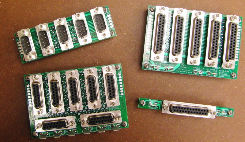
What the wiring hub looks like. Actual size is 3.8" x 2.5".

AXIS.jpg


And a sketch up of the typical application, plus ground and voltage distribution:

AXIS_application.jpg


Here's what it does:

AXIS-15A

Supports:

-The connection of EFIS system serial buses together. In the example, the SkyView system's 5 serial ports, plus the SkyView GPS power/ground connections. This occupies 12 of the 15 signal buses on the backplane, and two connector positions.

-Multiple instrument connections without wire splices. Normally, only one connector position is required to support all of the connected instruments unless there is a need to fan-out to more than one instrument per signal by using additional connectors. Some applications can allocate the unused signals available on the backplane to communicate independently of the EFISs.

-Facilitate adds, changes and upgrades. Simply by swapping connector pins to other positions, a wiring change can be made in a few minutes without cutting and splicing.

-Simple access for debugging.

-Convenient ground or power busing for avionics instruments using dedicated 15-pin DSub connectors and fast-on tabs.

-The ability to add small circuits on board by providing signal access and a prototyping area. For example, signal monitoring lamps can be wired in to provide visual indication of signal status.

Thanks! Please contact me if you have any feedback or want to be on the product notification list.

Vern Little
 
Hi Vern,

I'm a fan of anything that makes wiring easier! :D We often see the Garmin 430 aviation format output, for example, going to 4 or 5 different units.

Two things I would be concerned about:
1. You've essentially added an antenna to each of the serial lines which can emit or receive interference to/from the data lines.
2. If the single ground wire fails all the avionics fail.

Good feedback, Marc.

To address the serial line issue: Dynon uses unshielded wires for their serial links, so the addition of 3" of wire should not make a big difference in EMI, particularly at the slow data rates used and the controlled slew rates of RS-232C signals. It's also possible to devote 2 wires to each serial line, and carry through a shield connection per signal. This consumes more of the bus, but was considered in the design. Ideally, a larger bus would be required (AXIS-25A?). Even though I show Dynon's EFISs, the AXIS-15A is also compatible with most other EFIS systems. It's just that the Dynon Systems have so many interconnects, with both RX and TX lines from two systems tied together.

As for the ground wire failure scenario, it's possible to split the bus into two-- one feeding eight grounds and the other feeding seven with discrete ground connections through the fast-on tabs. Then, you feed primary instruments from one of the split buses, and the back-up instruments from the other split bus. This can be continued by dedicating the second of the bottom connectors to ground buses as well (instead of the power buses shown), thus providing four discrete ground buses with individual fast-on connections and wires to a central ground point.

One thing I didn't mention was that if you are fanning out to 4 or 5 loads, you don't need 4 or 5 additional connectors. If there are unused signal traces, the active signal can be jumpered using the holes at the extreme left or right of the board (among other places). This provides multiple traces with the same signal, thus allowing multiple instruments to connect to the signal on one connector.

Thanks, Vern
 
my 0.02 cents

I am a big fan of using a Hub for connecting modern days avionics. It makes wiring a breeze, but more importantly it makes addition or changes just as easy. I have used a Approach fast hub and with all the avionics that I put in my panel, I thought I would never want to change any thing. Well since, there has been additional "goodies" like Zaon that I have added and the installation was just as easy as connecting a plug to the hub.
 
Cool

Vern,

That's pretty neat. However, it seems like it might be nicer to have many more connectors so that each device could have it's own cable rather than multiple devices sharing an octopus cable.

Just a thought,
 
Vern,

That's pretty neat. However, it seems like it might be nicer to have many more connectors so that each device could have it's own cable rather than multiple devices sharing an octopus cable.

Just a thought,

Thanks, Mike.
I considered this, and it's quite possible.

If you look carefully, it's easy to daisy-chain boards, either through 15-pin Dsub jumper cables, or by using the row of holes labelled Jumper Block L (or R) on each end of the board and soldering wire jumpers in place to an adjacent board. That allows expansion of the ports in chunks of five. For example, you can string three boards together to get 15 individual bus connectors.

Thanks, Vern
 
AXIS-15A Update: protos in-house

Hi Folks, protos have arrived early. Here's a picture. More information forthcoming after Christmas.

Thanks, Vern

AXIS-15A_photo.jpg
 
Something I've often thought of, but never asked before, is how do these wiring hubs actually "know" what's being plugged into them, and are thus wired internally to suit the equipment?

Or to put it simply, I have Skyview, GNS430 and a GMA240 (for eg.) Can I use the same hub as someone who has a GRT EFIS, KLN-90B and a PMA-8000 audio panel? I'd have thought each of the manufacturers would have a different pinout for their products.

Hi Rob, if you look at the board layout, you'll see that it's essentially a backplane... all of the corresponding pins are wired together on the connectors. Thus, if you put a GPS signal on pin 1 of J1, it appears on pin 1 of the other connectors J2...J5. If you need this GPS data for a transponder, an EFIS and an ELT, for example, you can connect them to pin 1 on J2, J3 and J4 for example. Signals that have only one load can all be wired to the same connector if you wish.

So the answer to your question is that all of the intelligence is in your wire harness that connect to the AXIS-15A. If you need to make a change, you can do so by swapping pins in the connectors, or adding a new connector/harness with the additional connections.

Essentially, it replaces splicing a bunch of wires, then cutting them apart and putting new splices in when you make changes or upgrades. This is more elegant and reliable.

Vern
 
vlittle said:
Hi Rob, if you look at the board layout, you'll see that it's essentially a backplane... all of the corresponding pins are wired together on the connectors. Thus, if you put a GPS signal on pin 1 of J1, it appears on pin 1 of the other connectors J2...J5. If you need this GPS data for a transponder, an EFIS and an ELT, for example, you can connect them to pin 1 on J2, J3 and J4 for example.
Im always amazed how I constantly manage to overlook the simplest of things... :eek: Looking at the PCB layout it makes perfect sense.

Many thanks for that.
 
The AXIS-15A now available as a product

Good news on the AXIS-15A front. I received a lot of positive feedback on this device, and we've now released it as a product. We have inventory and are ready to ship.

Link here to the announcement, or go to our site for more general information.

Thanks, Vern
 
old product :)

According to your announcement it has been out of a year already. Aren't year changes fun?
Bill Greenley
 
More products from the Vx Skunkworks

Not content with the AXIS-15A (as discussed above), I've developed 3 more products in the family:

AXIS-9A: Dynon SkyView Network Wiring Hub
AXIS-25A: 25-wire bus. Like the AXIS-15A but using 25-pin connectors and no power/ground blocks.
GBX-25A: a 25-wire ground block.

AXIS-ALL-photo.jpg


Also, the AXIS-15A has been modified to use edge connectors for board-to-board expansion, rather than rows of holes for discrete jumpers.

More information available on our website: www.vx-aviation.com

And thanks to all of our customers that made the AXIS-15A the fastest selling new product in our history.

Vern
 
Back
Top