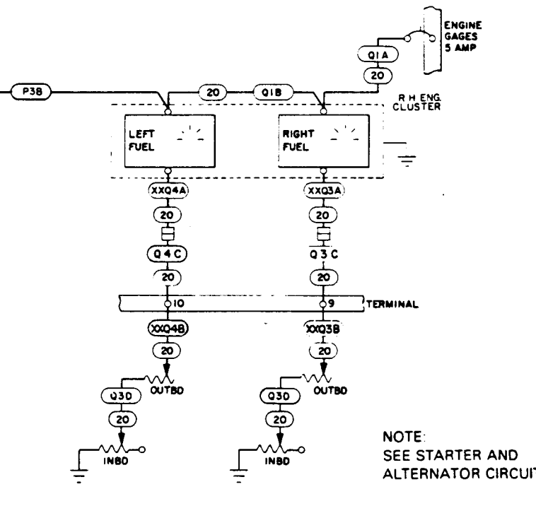
I'm installing the RV-10 ER tanks from Sky Designs and at the moment I'm planning to use the Garmin G3X avionics. I am using the Stewart Warner 385 series floats that Vans sells.
Since I am about to proseal the floats to the baffle I want to know if there is any surgery required on the internals of the sender so I don't have to find out later and cut them out. My preferred approach is to just hook the one output wire from the outboard sender to the output wire location of the inboard sender and then run the single wire from that inboard sender output to the avionics. It'll make wiring simple and removing the tank simple, if required.
Is my preferred approach the best (most accurate, or not far off the most accurate option)? Will it work if I change my mind and go with Dynon or something else?