

jeffw@sc47
Well Known Member
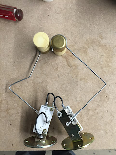
I messed up the two float wires supplied with the sender units yesterday. Bent the first one "precisely" as shown in the diagram Page 18-10. My definition of "precisely" means that I fabricated a plywood jig to hold the wire along the 4" lengths very tight and got the 90 degree bends sharp with a small radius, the arm lengths were as close to the diagram specs as anyone could get them.
After bending the first, the clamp loop around the float interfered with the #2 rib and would not work freely. Tried to put a couple of bends in the leg coming from the sender unit to shorten the leg - kind of fixed it but not good solution. So I bent the other wire per the design specs thinking I the first was not precise enough. Same outcome and the second one was no better than the first - perfect in my opinion. Second also interfered with the rib.
So I got out my measurement tools, my CAD tools, my scanner, and my kit of software. In the diagram (Figure 1, page 18-07) showing the arc swing and scaling of the design I found a couple of discrepancies.
My findings and solution - you will need to decide for yourself whether I got this correct or am off base:
This I Believe - scrutinize what I found and if you see that I am wrong please let me know.
1- The distance between the facing surfaces of the ribs each side of the compartment where the float is located is approximately 8 7/16", almost 1/2" less than the space indicated (8 29/32") in the diagram (Fig 1, 18-07).
2- The arc of the swing designed is not indicated correctly in that the center-point of the swing shown is approximately 3 1/2" beyond the presumed c-p shown at the sender. The arc swing as I calculate is 6 7/16" with the center of the swing at the post inserted into the sender unit.
3- In the diagram, I created the pdf scan (then scaled to actual size) is over-laid with CAD construction - BLUE lines highlighting the designed tank ribs locations, floats, and swing arc; and the RED lines indicate the float wire bends as designed on Page 18-10 with their swing arc.
 [/URL][/IMG]
4- The interference point of the actual swing arc and the actual location of the tank rib corresponds exactly with what I found when bending the wires as designed and temporarily installing the sender in the tank. I inserted some 1/32" thick paper shims to simulate the ProSeal gasket thickness.
5- Also, I believe that the bend diagram on page 18-10 showing the 1/2" leg at the sender end of the wire is bent the same direction relative to the float end clamp for both float wires. At first I thought that it would be opposite the left float and that was part of the reason the first wire was discarded. I am still trying to convince myself of that. This float wire bending is akin to a Rubics Cube.
I found that Van's does have a supply of replacement float wires, so I ordered 3 wires to do-over the bends, at $5.50 each. I believe that if I shorten the 4" legs by 1/16" - 3/32" each, the float will clear the rib and I will have the 1/16" clearance called for top and bottom from the skins.
After bending the first, the clamp loop around the float interfered with the #2 rib and would not work freely. Tried to put a couple of bends in the leg coming from the sender unit to shorten the leg - kind of fixed it but not good solution. So I bent the other wire per the design specs thinking I the first was not precise enough. Same outcome and the second one was no better than the first - perfect in my opinion. Second also interfered with the rib.
So I got out my measurement tools, my CAD tools, my scanner, and my kit of software. In the diagram (Figure 1, page 18-07) showing the arc swing and scaling of the design I found a couple of discrepancies.
My findings and solution - you will need to decide for yourself whether I got this correct or am off base:
This I Believe - scrutinize what I found and if you see that I am wrong please let me know.
1- The distance between the facing surfaces of the ribs each side of the compartment where the float is located is approximately 8 7/16", almost 1/2" less than the space indicated (8 29/32") in the diagram (Fig 1, 18-07).
2- The arc of the swing designed is not indicated correctly in that the center-point of the swing shown is approximately 3 1/2" beyond the presumed c-p shown at the sender. The arc swing as I calculate is 6 7/16" with the center of the swing at the post inserted into the sender unit.
3- In the diagram, I created the pdf scan (then scaled to actual size) is over-laid with CAD construction - BLUE lines highlighting the designed tank ribs locations, floats, and swing arc; and the RED lines indicate the float wire bends as designed on Page 18-10 with their swing arc.
4- The interference point of the actual swing arc and the actual location of the tank rib corresponds exactly with what I found when bending the wires as designed and temporarily installing the sender in the tank. I inserted some 1/32" thick paper shims to simulate the ProSeal gasket thickness.
5- Also, I believe that the bend diagram on page 18-10 showing the 1/2" leg at the sender end of the wire is bent the same direction relative to the float end clamp for both float wires. At first I thought that it would be opposite the left float and that was part of the reason the first wire was discarded. I am still trying to convince myself of that. This float wire bending is akin to a Rubics Cube.
I found that Van's does have a supply of replacement float wires, so I ordered 3 wires to do-over the bends, at $5.50 each. I believe that if I shorten the 4" legs by 1/16" - 3/32" each, the float will clear the rib and I will have the 1/16" clearance called for top and bottom from the skins.
")

