What's new
Van's Air Force

Don't miss anything! Register now for full access to the definitive RV support community.

Elevator Tips Attachment Question

cderk

Well Known Member
*** Update ***
Van's Tech Support responded first thing this morning. Looks like I have it correct. Sterling says:
"The assembly order of the parts in your picture is correct. Rib inside of spar with counterbalance skin over the top, the main elevator skin will later be applied over the top of this."

Good evening all -

I have a quick question for the braintrust...

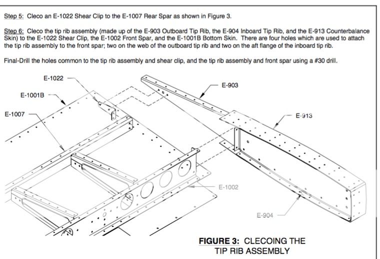
I'm working on putting my elevator together, and for the life of me, can't get a clear understanding from the instructions. I'm looking at Page 9-6, Step 6... attaching to elevator tip rib attachment.

There are a number of mating surfaces, and I'm not sure which parts lay on top or under the others. I think I have it the way its supposed to be, but I can't be sure.

Thanks
Charlie


Last edited:
I think we all scratched our head at that step. Does this photo help?

DSCN6733.jpg
 
Thanks Andy - I wish it did. What I'm really wanting to see is how the mating surfaces lay on top of each other. I shot an email off to Van's tech support - hopefully they'll come back with some easier to understand instructions for me.

Regards,
Charlie
 
I think you have it mostly right.

The drawing shows the E-1002 sliding behind the E-904 and the flange of the E-904 mating holes on the E-1002.

The flange of the E-1002 would then be attached to the E-903. No mating holes are shown on the drawing, but they may be present on the E-903.

I think you have the E-913 mispositioned though. The drawing shows the center row of holes aligned to the E-904 rib.

These are little details that you will learn to pick out of the drawings.
 
Last edited:
I think you have the E-913 mispositioned though. The drawing shows the center row of holes aligned to the E-904 rib.

These are little details that you will learn to pick out of the drawings.

Ray -
Take another look... I don't think you are correct. I think the center holes are aligned with the other part - 903.

charlie
 
Center row of holes does line up with 903...but the flanges of the spar (E1002) should be inside both 904 and the skin (E913), not wedged in between.

==dave==
N102FM
 
Sorry guys I was trying to do this on my phone on the train this morning. I was having trouble scrolling between posts.

I agree that the E-1002 flange should be inside the E-904 flange. I didn't see this before, but that will allow the E-913 to sit flat on the E-904 and E-903 flanges.
 
Center row of holes does line up with 903...but the flanges of the spar (E1002) should be inside both 904 and the skin (E913), not wedged in between.

==dave==
N102FM

Are you certain of that? Further in the instructions it says that the flanges of the spar are not at 90 degree angles - they're at 96 degrees. In previous instructions it says to ensure that the tip flanges are at 90 degree angles. that tells me the opposite of what you're saying.

...not to mention that Van's tech support says "Rib inside of spar with counterbalance skin over the top"

Thanks
Charlie
 
Last edited:
Well, maybe I did it incorrectly, but I checked at the hangar this evening and the spar is clearly inside the E-904 tip rib. A couple of pages later in the plans, the riveting order has you putting the strip on around the two ribs before attaching it to the spar, so you will be trying to wedge it in there. The only other difference I can see is with the spar on the outside of the tip rib the skin is one layer closer to the spar.

As far as the angles go, the spar flange angle is perpendicular to the rib flange, and matches the elevator profile, as does the tip rib, so that shouldn't be a concern...

Don't know if that helps or not, but that's how mine went together, FWIW.

==dave==
N102FM

Thanks Dave... I'll have to read a little further. I guess what I meant is that the spar is angled out and the ribs are at 90s, so to me, I would assume that was done so that the ribs fit inside the spar.

Regards,
Charlie
 
Please look back at page 9-1. There will be a little gap in the counterbalance skin as it passes over the spar.

NM. I see Vans responded with a similar statement.
 
Last edited:
Thanks for posting this, Charlie!

I was at this step tonight and scratching my head as well on the stackup when I remembered this post!
 
That's why this site is so awesome! Can't imagine going through my build without folks to bounce things off of.

Thanks DR
 
Back
Top