What's new
Van's Air Force

Don't miss anything! Register now for full access to the definitive RV support community.

G3X OAT probe problem

Fredrik

Active Member
Good morning!

I've run out of ideas about why I don't get any OAT reading in my G3X system and I thought I let You knowledgeable guys have a go at it.

I'm in the final stage of panel upgrade and got everything hooked up, except for engine probes, A/P servos and other airframe hardware (still in workshop).

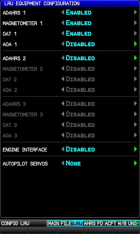
After powering up, everything is working as expected, except for the OAT probe (GTP 59).:mad:
I've disassembled, checked and reassembled the D-sub contact to the GSU 73 and the grounding of the probe and no obvious errors.

Now I pulled out the pins and measured the resistance and found the following:
between white (power) and blue (sense) leads - 0.3 ohm
between white and orange (low) leads - 535 ohm
between blue and orange leads - 535 ohm
no short between any lead and ground.

Is this normal readings for the probe, or do You think is it broken?

Thanks for any input on this!

Cheers,
Fredrik
 
Hello Fredrik,

Sorry to hear you are having trouble with your OAT probe installation. The GTP 59 is a pretty simple device so I bet we will be able to get it working. Here is some reference information on the GTP 59 that may be helpful:

1. The white (power) and blue (sense) wires are connected internally.
2. Between the blue (sense) and orange (low) wires is a 500-ohm RTD sensor.
3. Typical resistance between the blue and orange wires will be as follows:

-25 degrees C = 451 ohms
0 degrees C = 500 ohms
+25 degrees C = 549 ohms
+50 degrees C = 597 ohms

So, based on the measurements you've already taken, it sounds like your temperature probe is behaving correctly. (and also that it is a pleasant day in Stockholm!) So I would concentrate on the wiring between the GSU 73 and the GTP 59. Sometimes it can be useful to fabricate a short harness to connect the OAT probe directly to the GSU 73 connector, to make sure that the aircraft wiring harness isn't to blame. Don't forget to connect both ends of the wire shield as shown in the install manual.

If that doesn't work, please report back and we'll see what further steps need to be taken.

- Matt
 
I can't get mine to work either. I'm out of town right now but IIRC, my reading with an ohm meter are were in the 400's and the same on two of the wires and low numbers on the third. The wiring and pins were checked and verified correct multiple times. Good ring terminal ground to the airframe. I replaced the 20awg wire backshell ground wire I used with 16 awg per the manual. Nothing. I have no splices or connectors with the Garmin supplied wire. I tested and am getting 4.98 volts out of the GSU 73 pin 16 :confused:
When I get home I will recheck the wires with an ohm meter per g3xpert response and compare to current shop temperature.
 
Thank You Matt for quick reply. Yes is't quite fair weather here except for a recent TS.

The probe I got came pre-wired and sealed at the probe end. What I did now was to cut the 3-lead wire a foot shorter and crimped on new pins and a new pigtail to the shield. Same result as before.

As the wire harness I have, also have a lot of un-terminated engine probe wires, I configured the LRU "Engine interface: Disabled", but still no luck.

Here are some screenshots if it can assist in debugging:
20130616_192517.jpg

20130616_192542.jpg

20130616_192550.jpg

20130616_192233.jpg


Green check boxes except for Air data, which, as I understand, is necessary for magnetometer calibration.

Cheers,
Fredrik
 
Last edited:
Matt,

Now I have triple checked connections to the GTP 59 and still no luck.
Could I use the GSU 73 DataLogger to get some more clues for this?
It seems only to put out binary data.

/Fredrik
 
Hi,

I had similar problems with OAT, finally it was a cross wire, so please take your time and check those 3 wires.

Cheers,

Fernando
 
Hi Fernando,

Thanks for Your input.

My GTP 59 probe came sealed where the cable enters the probe with some black epoxi like material. I can't inspect that end without destroying the probe.

At the other end of the cable there are three pins that goes into the D-sub connector. I have taken them out several times and measured the resistance with similar result as described by Matt earlier. The three leads in the cable are color coded:white=power (goes to #16), white/blue=sense (goes to #15) and white/orange=low (goes to #35).

Do You mean that I should try to swap the leads, in contradict to installation manual, as if they have been wrongly connected at the probe end?

Where your color coding of the leads wrong?

/Fredrik

I am suspecting this also but am hesitant to swap wire color pin-outs contrary to the wiring schematic. The installation manual schematic shows a yellow/power-pin 16, blue/sense-pin 15, orange/low-pin 35. There is no yellow wire on the GTP59, just blue, orange, and white. I put white to power pin 16 per my schematic from Stein.
 
Now I have triple checked connections to the GTP 59 and still no luck.

Fredrik,

Sorry to hear you are still have trouble. I double-checked the pinouts in the installation manual, and confirmed they are correct and that agree with what you are using. Between the GTP 59 and connector P732 on the GSU 73, the blue wire connects to pin 15, the white wire connects to pin 16, and the orange wire connects to pin 35. I also obtained a new GTP 59 and GSU 73 and connected them together using this pinout, which resulted in a valid OAT reading. So, we can be pretty sure this wiring guidance is correct.

Since you have already determined that your GTP 59 is probably good, the next thing I would do is use your ohmmeter to measure the resistance between the three pins on the GSU 73's P732 connector (with the connector removed from the GSU 73). You should see a little more than 500 ohms between pins 15 and 35 and also between pins 16 and 35, and close to zero ohms between pins 15 and 16.

Another thing you could try is to carefully probe your GTP 59 wiring with a voltmeter, while it is connected to the GSU 73 and the GSU 73 is powered on. You will want to do this as far "downstream" (i.e. closest to the GTP 59) as you can. If you measure between the blue and orange wires, you should see approximately 85-90 mV at room temperature. Either 0V or 5V could indicate an open circuit somewhere.

- Matt
 
I tested and am getting 4.98 volts out of the GSU 73 pin 16.

I am suspecting this also but am hesitant to swap wire color pin-outs contrary to the wiring schematic. The installation manual schematic shows a yellow/power-pin 16, blue/sense-pin 15, orange/low-pin 35. There is no yellow wire on the GTP59, just blue, orange, and white. I put white to power pin 16 per my schematic from Stein.

David,

From what you describe it sounds like you have a wiring issue somewhere. Seeing 5V at pin 16 indicates that the GSU 73 is trying to drive current through the OAT probe, but there is no complete circuit. Typical readings here should be in the low millivolts range, not 5V.

The wire colors you mentioned sound like they came from someone else's schematic, not the G3X installation manual. You'll want to verify that the following wire colors on the GTP 59 connect to the following pins on connector P732 on the GSU 73:

P732 pin 15 - Blue
P732 pin 16 - White
P732 pin 35 - Orange

- Matt
 
Thanks for the reply Matt. I am using the wiring schematic from Steinair. They have the correct wire colors on their schematic that match the GTP 59 wire colors. The G3X installation manual has the yellow wire as the power wire for connector P732, pin 16, (though the connector that I have is J732) on Appendix C, page C-4, revision G. I just checked once again to be positive the wiring and pins are correct and they are. I also checked the GTP 59 wires with an ohm meter disconnected from the GSU 73:
Wht-Blue: .3
Wht-Orange: 539

Blue-Wht: .4
Blue-Orange: 540

Orange-wht: 539
Orange-blue: 539

There is 4.98 volts coming out of the GSU 73 female connector J732 pin socket #16. I am getting correct EGT and CHT readings.
 
Last edited:
Matt,

The resistance in the leads are as You specify (measured at the pins).

Next I carefully opened the cable about a foot from P732 connector, pulled out blue and orange lead, powered on and measured 87.6 mV between them.

What to do next?

/Fredrik
 
GSU73 OAT Input Tester

Fredrik and David,

If you wanted to test the GSU73 OAT probe interface, you could build a quick OAT tester like I did this morning.

550OhmOATTester.jpg


I took a 550 ohm resistor (anything around 500 ohms will do), soldered two wires on one end and one wire on the other end.

Insert the two wires on one end of the resistor into pins 15 and 16 on the P732 connector and plug the single wire on the other end of the resistor into pin 35 on the P732 connector. If you leave the connections un-insulated like this, make sure nothing is shorted to ground before applying power to the system.

I went from a red-x'd OAT reading (with nothing plugged into pins 15,16,35) to everything OK reading a steady 76 degs F on the PFD in just a couple of seconds after turn on.

Hope this helps.

Thanks,
Steve
 
Last edited:
Hi Steve,

Thanks for Your suggestion.
I made up a fake probe according to Your description and tested it.

Still got a red X. :confused:

/Fredrik
 
Fredrik and David,

If you wanted to test the GSU73 OAT probe interface, you could build a quick OAT tester like I did this morning.

I took a 550 ohm resistor (anything around 500 ohms will do), soldered two wires on one end and one wire on the other end.

Insert the two wires on one end of the resistor into pins 15 and 16 on the P732 connector and plug the single wire on the other end of the resistor into pin 35 on the P732 connector. If you leave the connections un-insulated like this, make sure nothing is shorted to ground before applying power to the system.

I went from a red-x'd OAT reading (with nothing plugged into pins 15,16,35) to everything OK reading a steady 76 degs F on the PFD in just a couple of seconds after turn on.

Hope this helps.

Thanks,
Steve

Thanks Steve. I will do this when I get back home Friday.
 
Fredrik and David,

We sent you emails, but not sure you received them.

Please email us at the address below so we can work with you directly to get this resolved quickly.

Thanks,
Steve
 
This issue was solved by software downgrade (7.40), configuration and then back to software v. 8.00.

Thanks to G3X support!:)

Cheers,
Fredrik
 
Fredrik and David,

We sent you emails, but not sure you received them.

Please email us at the address below so we can work with you directly to get this resolved quickly.

Thanks,
Steve

I sent you an email with current address. Thanks Steve.
 
Back
Top