

Rough surface
Member
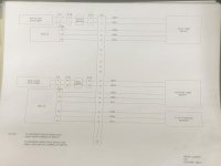
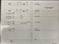
With the G3X auto pilot off my Ray Allen trim servos operate normally with the 4 way hat on the pilot stick. I have a single toggle switch to power the Garmin GSA 28 servos and as soon as power comes on for the servos it pops the fuse for the trim servos. My system calls for a 1 amp fuse for both pitch and roll trim servos (same circuit). I have put a 4 amp fuse in place and it still immediately trips the fuse when the servos are powered up. I have a G3X with GFC 507 controller, new system not yet flown.
I have pinned out all connections and the wiring is good. With the GSA 28’s off (no power) the Ray Allen trim systems operates normally. This confirms the wiring, in my mind. Is there a spike when the GSA 28’s see power that trios the fuse? Autopilot also works and checks fine but won’t auto trim because the trim motors are disabled with the blown fuse.
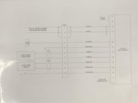
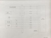
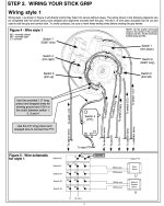
The relays are not required because I do not have the trims wired to the co-pilot stick. Just one stick is in control. RA stick grip is the G307, wiring attached below
RV-8A
I have pinned out all connections and the wiring is good. With the GSA 28’s off (no power) the Ray Allen trim systems operates normally. This confirms the wiring, in my mind. Is there a spike when the GSA 28’s see power that trios the fuse? Autopilot also works and checks fine but won’t auto trim because the trim motors are disabled with the blown fuse.
The relays are not required because I do not have the trims wired to the co-pilot stick. Just one stick is in control. RA stick grip is the G307, wiring attached below
RV-8A
Attachments
-
 8926F204-E665-4EBC-B99F-31D1E6111612.jpg223.9 KB · Views: 173
 -
 A1FC930B-95DD-420F-8911-6C570897BAB2.jpg300.5 KB · Views: 172
 -
 4D3EF474-59BC-486E-962A-6D59F49E805B.jpg104.3 KB · Views: 155
 -
 16687B60-8A8E-40C7-809F-96F452ECF2B4.jpg110.6 KB · Views: 144
 -
 Screen Shot 2021-12-19 at 5.31.18 PM.jpg350.5 KB · Views: 154
Last edited:


