I'm planning wiring for a G3X system and looking at backup rs-232 data paths - confused by how the RS232 works (if it needs a dedicated ground).
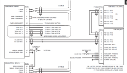
In some diagrams of the G3X manual, such as on 27-7 for the path between the GSA28 and the GMC307 or the GMC307 to the GDU, it shows the rs-232 as a 2 core shielded wire (shield grounded to the connector at both ends) and does not use any "SIGNAL GROUND" pins, or 3rd wire for ground.
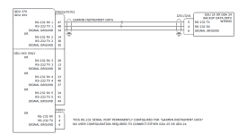
In other areas, like the GDU to the GEA24 such as on 27-11, it shows the use of a 3 core shielded wire (utilising a "signal ground" pin at each end), with the shield ground to the connector at both ends as well.
Now on the GEA24, J241 connector there is no signal ground pin!
Do i use a 2 core wire for this? or do i use a 3 core wire and connect the "signal ground" pin on the GDU to either "ground" pin on the GEA 24? (power ground?)
I guess a basic question - what is a "signal ground" pin? Is this just a pin which is grounded to the unit internally? (aka the same as the power ground etc).
In some diagrams of the G3X manual, such as on 27-7 for the path between the GSA28 and the GMC307 or the GMC307 to the GDU, it shows the rs-232 as a 2 core shielded wire (shield grounded to the connector at both ends) and does not use any "SIGNAL GROUND" pins, or 3rd wire for ground.
In other areas, like the GDU to the GEA24 such as on 27-11, it shows the use of a 3 core shielded wire (utilising a "signal ground" pin at each end), with the shield ground to the connector at both ends as well.
Now on the GEA24, J241 connector there is no signal ground pin!
Do i use a 2 core wire for this? or do i use a 3 core wire and connect the "signal ground" pin on the GDU to either "ground" pin on the GEA 24? (power ground?)
I guess a basic question - what is a "signal ground" pin? Is this just a pin which is grounded to the unit internally? (aka the same as the power ground etc).