For all three of my RV projects the design allows for full panel removal in just a few minutes. This provides for easy maintenance, panel updates and such.
The trick it to take the time now to identify what stays in the plane and what comes out when the panel is removed. For example stuff that stays in the plane are all the non-avionics wiring, the remote avionics (XPDR, COMM #2, ARINC, EMS Module) and most breakers. The stuff comes out of the plane are the panel itself and all the interconnecting wiring between the GTN-650 and the Audio Panel.
The breakers on the panel are only associated with the GTN-650 and the Audio Panel.
Panel to plane connections are all D connectors except for one 0.093” pin Molex that provides power to the panel mounted breakers and associated aircraft ground.
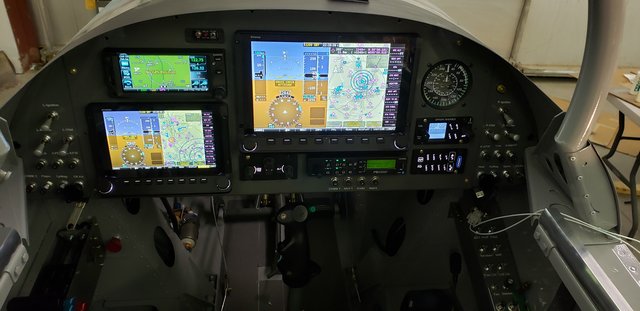
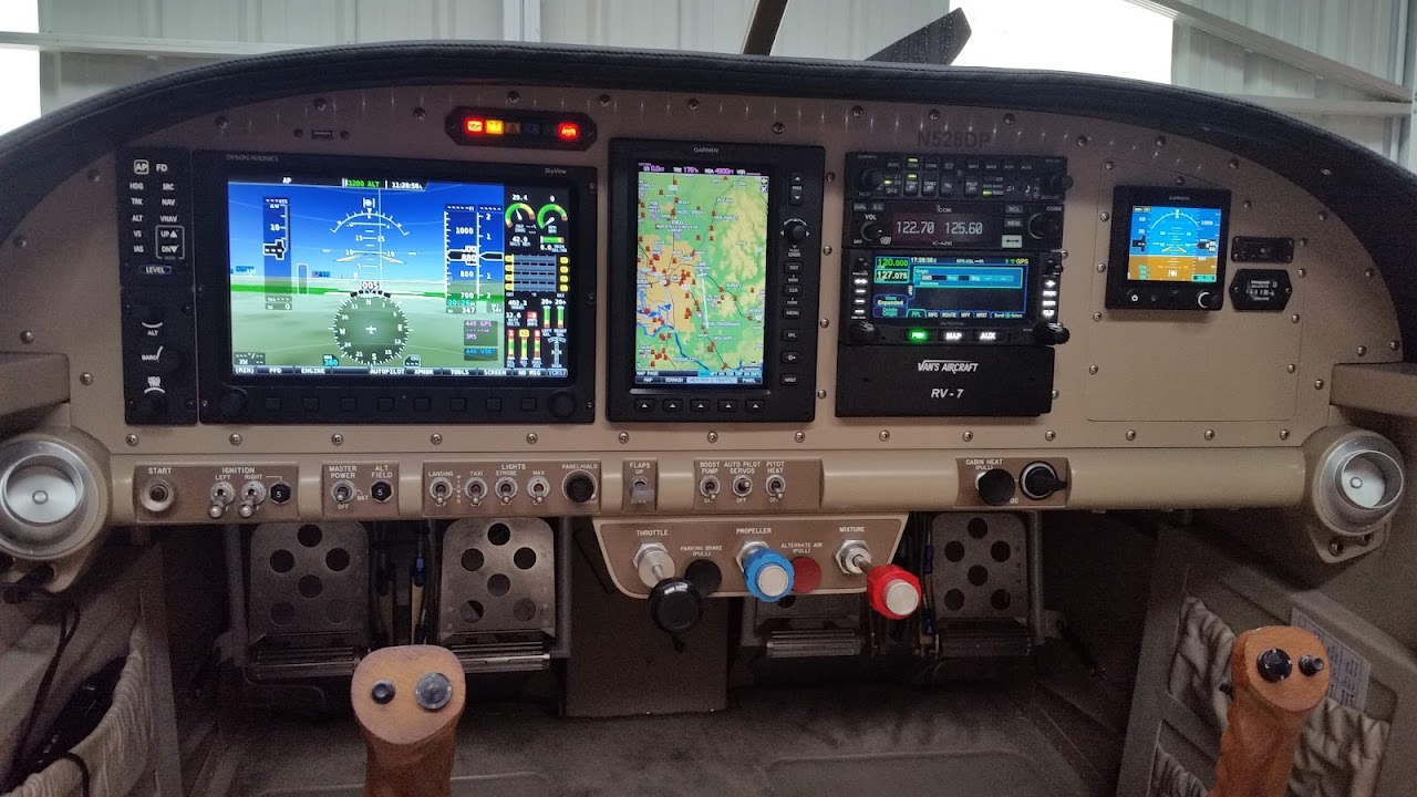
This is the panel:
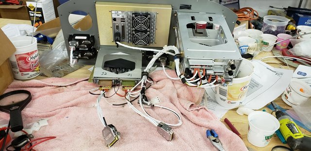
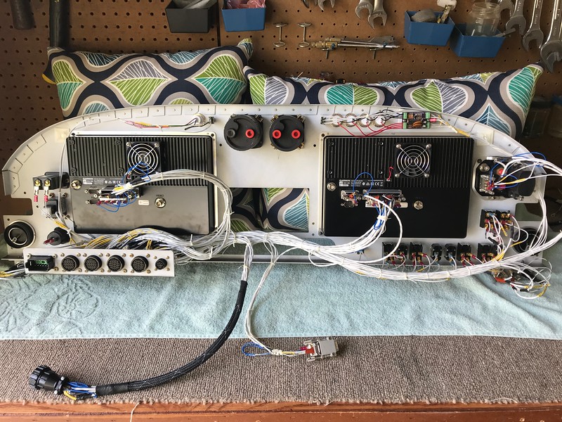
This is the panel out of the plane:
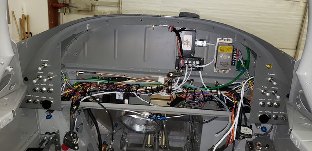
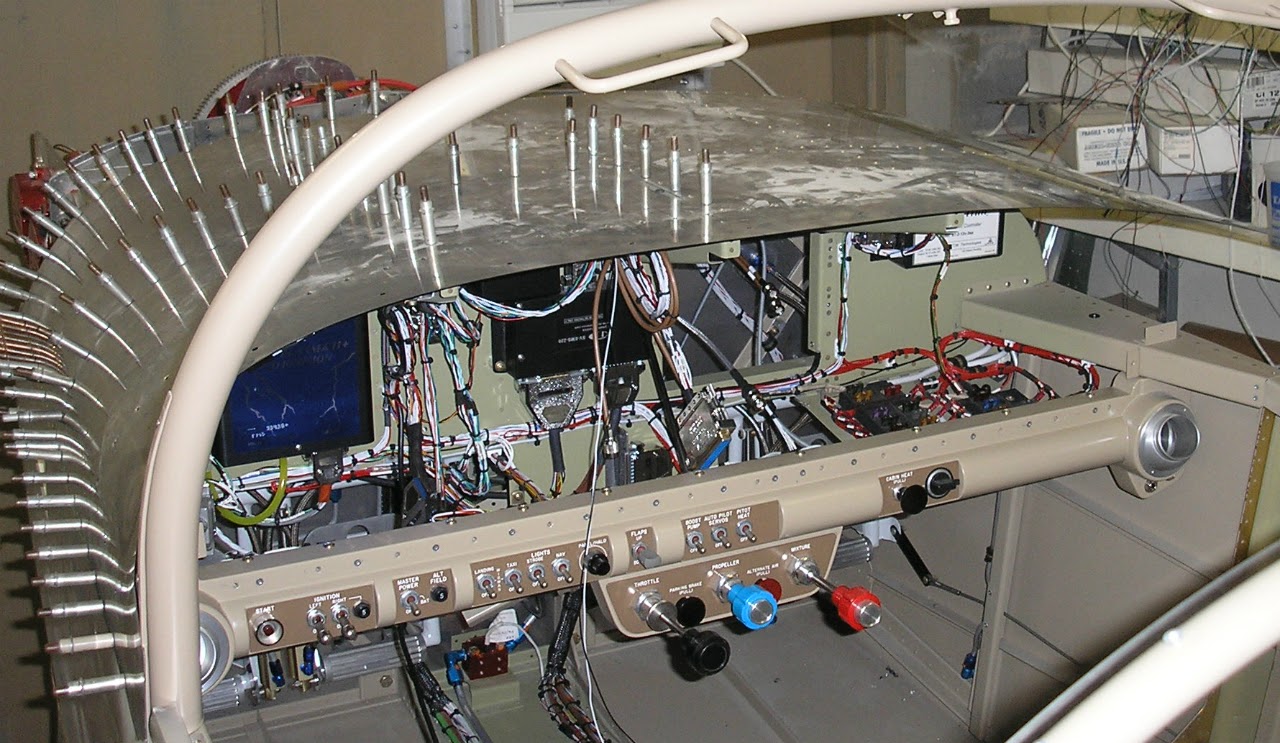
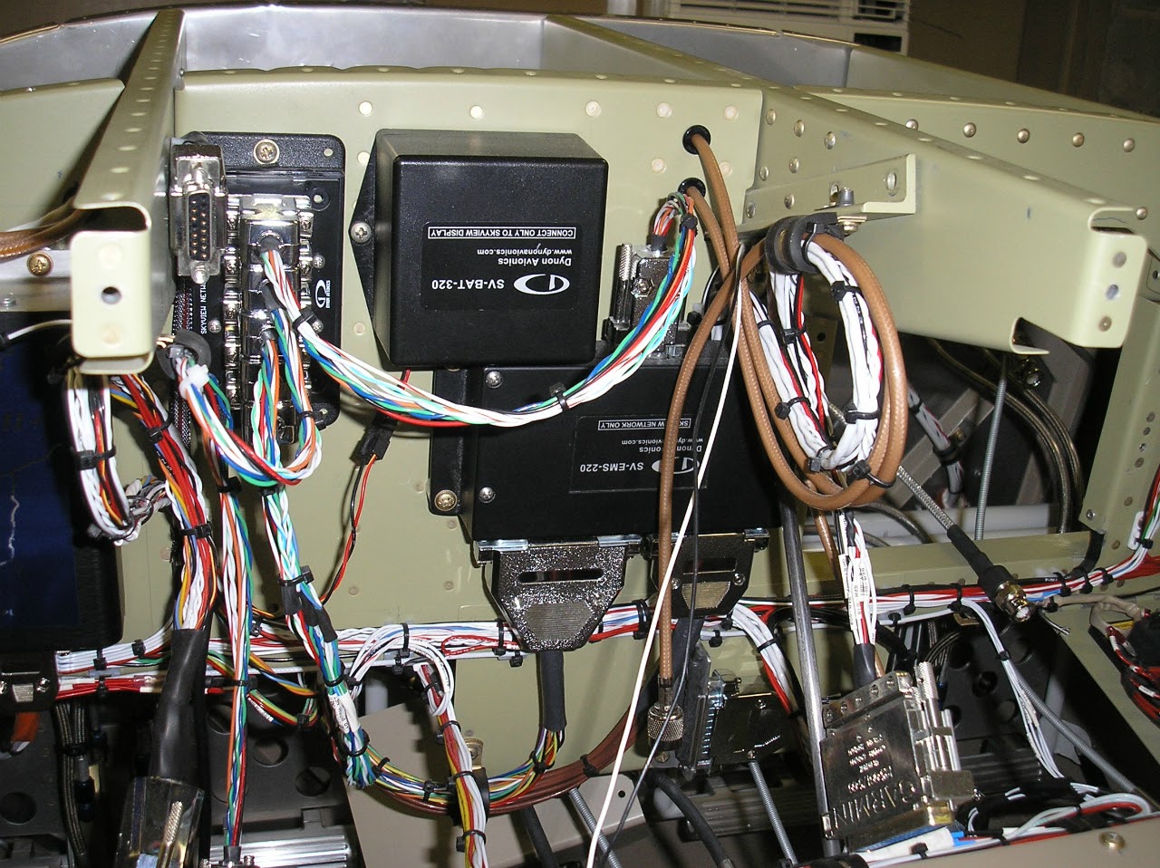
This is a look behind the panel. On the bottom you can see the XPDR, Comm #2 and the EMS module. On the top is the ARINC, the B&C voltage regulator, a SkyView network hub and a dimmer module.
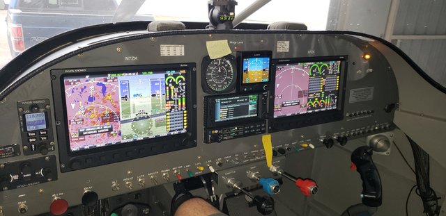
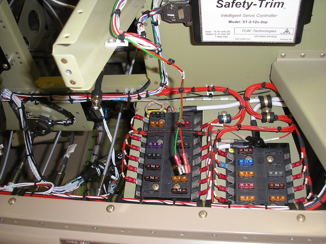
For the RV-8 the side wings are perfect to mount all the switches and breakers you need - all stay in the plane when the panel is removed.
For planes like the RV-10 the bottom apron provides for mounting switches, breakers and such:
A couple of design principles:
- Never on your back with your head under the panel.
- No matter how well you think things out, you will make changes and updates to you panel. Plan on that now. The first RV (RV-8A) now flying for 20 years is on panel #5. The above RV-10 panel is the second panel, and it was changed last year to reposition the SkyView autopilot module to a better spot.
Carl