
Van's Air Force
You are using an out of date browser. It may not display this or other websites correctly.
You should upgrade or use an alternative browser.
You should upgrade or use an alternative browser.
Autopilot Disconnect Button Loose
- Thread starter rv12is
- Start date


Tony Kirk
Well Known Member
AP Disconnect Switch Mount
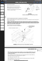
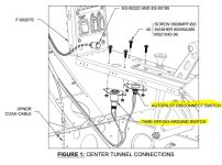
The mounting plate with the larger hole is for the TO/GA - Take Off / Go Around switch in the Garmin Nav/Com (IFR) avionics package. There is a different mounting plate with a smaller hole for the Autopilot disconnect switch.
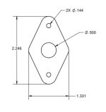
You need the "ES-60002B" plate. You can get one from Van's or make it yourself from some .032 2024-T3.
.
The mounting plate with the larger hole is for the TO/GA - Take Off / Go Around switch in the Garmin Nav/Com (IFR) avionics package. There is a different mounting plate with a smaller hole for the Autopilot disconnect switch.
You need the "ES-60002B" plate. You can get one from Van's or make it yourself from some .032 2024-T3.
.
Attachments
rv12is
Active Member
The mounting plate with the larger hole is for the TO/GA - Take Off / Go Around switch in the Garmin Nav/Com (IFR) avionics package. There is a different mounting plate with a smaller hole for the Autopilot disconnect switch.
You need the "ES-60002B" plate. You can get one from Van's or make it yourself from some .032 2024-T3.
.
Thank you very much. That's exactly the information I was looking for. I'm guessing SteinAir installed the wrong plate while building my harness. (Their customer support has been great, but their QA leaves a lot to be desired.)
I don't see "ES-60002B" listed in Van's store, so I'll probably just fabricate one. Unfortunately, replacing this plate will require me to remove and resolder the button. However given the quality of soldering in other places on the harness, this is probably a good thing.
")
.jpg")
--edit--
Heat shrink was removed for inspection prior to taking the above picture.
Last edited:
rv12is
Active Member
Wow! they could have at least put some shrink tube over that mess to hide it!
They did. This picture was taken after I had removed the heat shrink to inspect these connections. I've edited my previous post to avoid potential confusion.
rv12is
Active Member
Stein soldered that.....?
Yes. Other than removing heat shrink to inspect, this is how it came.
There was no wetting of the solder to the wire at all. The only electrical connection came from the mechanical bending of the wire around the terminal and secured with heat shrink. Lights immediately flickered on power up. I have now idea how this made it through any sort of QA check.
rileyspoon
Active Member
Stein Air QA issues
Most of my harness was well made and carefully labeled however I spent two weeks of wasted time thinking I had a bad fuel pump. I even sent them off to Lockwood only to figure out Stein had reversed the polarity on one of the power leads. I sent them an email describing the issue and never heard a peep.
Most of my harness was well made and carefully labeled however I spent two weeks of wasted time thinking I had a bad fuel pump. I even sent them off to Lockwood only to figure out Stein had reversed the polarity on one of the power leads. I sent them an email describing the issue and never heard a peep.
rv12is
Active Member
I sent an email to SteinAir about this. Not asking for anything, but just letting them know my harness was built with the wrong plate in case they wanted to check this on future builds. About 20 minutes later got a reply offering to send me a replacement plate. They also suggested it might be possible to notch the plate and just slide the wires through the notch, instead of needing to resolder the switch. I took them up on their replacement plate offer and thanked them for the notch suggestion. Also let them know that I would likely resolder as I wasn't happy with all of the solder joints. Now there's a mounting plate and a new button heading my direction.
.jpg")
Unfortunately this isn't my first problem with my harness. But I often say mistakes can happen, it's how a company responds to them that matters.
SteinAir support continues to be excellent and exceed my expectations.
Unfortunately this isn't my first problem with my harness. But I often say mistakes can happen, it's how a company responds to them that matters.
SteinAir support continues to be excellent and exceed my expectations.
bkc3921
Well Known Member
Wow....
Thanks to all for the heads-up. My avionics kit is due this month after a one year wait. Now, you can bet I'll be checking it like a diamond merchant.....
Everything they have done for me in the past has been top-notch, including their customer service. Let's hope this this is a fluke, and not becoming their standard work.
Stein soldered that.....?
Thanks to all for the heads-up. My avionics kit is due this month after a one year wait. Now, you can bet I'll be checking it like a diamond merchant.....
Everything they have done for me in the past has been top-notch, including their customer service. Let's hope this this is a fluke, and not becoming their standard work.
Quality Control Procedures
Hey All,
I want to chime in and say that we take our quality control very seriously. We have been working with the original poster to make sure that his harness is corrected and that he has everything he needs to ensure that his issues are corrected. Beyond that we immediately took a closer look at our QC processes to identify holes in them that allowed this to happen, and took corrective action. The core process that allowed this to happen was a combination of unique circumstances, and a flaw in our QC process - we had been shrinking down the heat shrink prior to our visual inspection. The contact on those posts was sufficient to pass the electrical testing, but obviously was not anywhere near acceptable. This process has now been changed so that every solder joint is inspected before the heat shrink is shrunk down.
As you are aware these harnesses are large and complex, and doing them right is what we specialize in and what we are being paid to do. We have multiple QC check points set up through out the build / test process and are constantly working to improve and evolve these processes.
Here is a window into the major steps in our quality control process.
Step 1: Before the harness is assigned
Before a project is assigned to a technician, all avionics, and Van's supplied parts are inventoried. SteinAir supplied parts are added to the cart. At this time it is verified that all avionics have been received, and the serial numbers are logged into our system. If there are any discrepancies or missing parts, this is addressed before the project is assigned to the technician.
Step 2: Initial technician steps
1. Inventory the avionics, parts, and pieces to confirm all required components are present. We do not re-inventory Van's supplied parts for the builder, just parts we integrate into the harness: i.e. flaps switch, switch plates, power modules, avionics, backup battery, ect. Any missed discrepancies are reported at this time so they can be addressed before the harness is removed from the wiring board.
2. Log on to the Van's cloud to ensure there has not been a revision update. If there has been, the newest drawings are downloaded, and the wiring board is changed out to a new copy.
Step 3: Pre-testing Inspection:
When the harness wiring has been finalized, but before it has been taken off of the wire board I conduct a visual inspection of the harness. I inspect the harness for the following things: Harness cleanliness/aesthetic appearance, Harness length accuracies matched against the board it is on, lacing knot integrity, solder sleeve/joint integrity, crimp integrity on all pins - visual inspection as well as a pull test, visual inspection and pull test of all connectors and contacts-looking for deformed pins or crimps, loose contacts, or any other inaccuracies, pull and test the COAX cable connections. We are now also taking this time to fully inspect all hand soldered joints, then shrinking down the heat shrink. At this time I also make a point of inspecting the fuel pump wires, ensuring A to A and B to B, as well as inspecting the X3 connector contacts and splice and HIC connector Molex with extra attention. This entire review is conducted on the harness board, and by a 3rd party, usually myself, so that it is a fresh pair of eyes on the harness.
Step 4: Configuration:
The harness is then removed from the harness board, and prepared for testing. This includes hooking up all avionics, the antennas, and the power module / HIC modules. We use the Coax cables that are bundled with the harness for testing.
Once the harness is all set up, the last thing we do is hook up the power supply. This is to avoid power accidentally being applied before the harness is completely set up. We then apply power, load the most recent software, and configure the entire EFIS system. We have configuration files that are provided by Van’s but there are a few things we still need to input by hand.
Step 5: Testing Phase
1. Once all of the configurations have been input, we start by verifying that everything is communicating properly. Dynon and Garmin both have system information pages that will allow us to verify that the configurations that have been input are working. In this step we are primarily focused on network configurations: RS-232, ARINC, SV-Net or Can Bus. If these are not all working properly, we will not be able to progress until the system is communicating fully and all LRUs are identified and working properly. Once the system appears to be communicating properly on the status pages we then progress to verifying that each item is working properly.
2. Audio Check: The first thing we will do is to check the com/audio. The screen will be put into normal mode, and we will verify that the COM is being displayed, and that it can be tuned and controlled via the EFIS. We will then hook up a headset and verify that the intercom works, ensuring that two people can communicate back and forth. Once that has been tested, we will move on to a radio test. For this test we will transmit and receive back and forth from a handheld radio to each seat. All 3 push to talks and the both flip-flops are tested at this point. Once all external audio has been tested we put the screen back in configuration mode and use the built in alert audio test functions to test the unswitched audio wires.
3. Transponder: Once the audio has been tested, we move on to the transponder. Like the radio, this is verified that it is controllable via the EFIS screen. We then use our IFR-6000 test box (that we use for transponder checks in the hangar) to do a full transponder check.
4. Autopilot: We confirm that the control head and servos are communicating properly on the EFIS. We then check the A/P disconnect switch by highlighting each servo on the system info page and depressing A/P Disconnect one at a time. This will indicate that the discrete is working.
5. Backup battery: We test the backup battery by turning the power supply off with the backup battery armed. We then ensure that the correct messages are displayed. Once system power is restored we check again with the backup battery disarmed (to make sure it shuts off). We then apply power and check to make sure that the battery voltage displays as it should.
6. Power Module: The first thing we check with the power module is the switch functions on it. For the external lighting switches, we have a small harness to simulate the wings lights with small LEDs. For things like the master switch, we test this by hand with a multimeter. Next we will confirm that the dimmer is working properly across all avionics and switches. We will then check the EFIS screen to ensure that the voltages and current draw are displaying properly.
7. Sticks and Positions: Next we check that the trim motor is running constantly in the same direction with both sticks and that the trim position indicator on the EFIS follows along correctly. We then check the flap motor for operation and for the position indicator on the screen to follow it. We also have a fuel level sender that is hooked up and that we use to check fuel level voltage is being displayed.
8. Final Checkout: From here the technician will come and get me. I will walk through these test procedures again with them and double check that everything has been done and that it is functioning properly. Again I always like to be a second set of eyes on everything because with harnesses these large and complex, it is so easy to get tunnel vision and see what you expect to see, even with a checklist.
Step 5: Pre-shipment inspection.
Once the final check has been done, the technician breaks the system down by removing power and unhooking and storing all components. They then go through the harness and add the plastic backshells, which we leave off during testing to make it easy to check wires. Once this is completed, but before being packed I again come back to inspect the harness. I ensure all backshells and strain relief has been properly installed, and that all connectors are properly labeled. I also inventory all parts that need to be sent with, and again to a visual inspection of the harnesses. From here we box everything up and bring it to the shipping department.
Step 6: Shipping
The final step in our QB process is a final inventory and cross check of all components as they are packed into the box for shipment.
I genuinely want everyone here to know that we clearly have made mistakes we are constantly working to address them, and more importantly make sure that our customers are immediately taken care on, and that we do not make the same mistake again.
We at SteinAir care deeply about what we do, and the people we work with.

