What's new
Van's Air Force

Don't miss anything! Register now for full access to the definitive RV support community.

G5 - Nav AND Gps?

Flying Canuck

Well Known Member
Patron
First some background. I'm working on getting my operating conditions changed to remove the "VFR Only" wording (Canada) so I can do IFR in my newly equipped RV-9A. The TC inspector has been really good, but has expressed concern that my AVMAP EFIS Ultra isn't a backup for the CDI/VDI on my GPS 175 (in case I lose my single HDX display), and also that my AVMAP and my MGL Razor control head are too far apart (attitude/airspeed/altimeter and LOC/GS) to be usable for backup. They are looking for a 30 degree field of view.

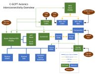
So, I'm looking into replacing my AVMAP EFIS Ultra with a Garmin G5. The only way that will satisfy both the concerns listed above is if I can send both my Nav LOC/GS (SL30 via RS232) and GPS 175 (via GAD 29 ARINC) to a single G5. The diagrams in the G5 manual shows that both items connect to the sole RS232 RX pin on the G5. Since the SL30 uses only RS232, can the GPS 175 connect with just a copy (splice, with Dynon ARINC) of the ARINC 429 OUT? I don't need to send anything from the G5 back to the GPS, so maybe I can skip the ARINC IN.

Any idea if this is possible? I'm open to other product suggestions too.
 
GAD29B will get you the 429 interface you need to get data from the 175 to the G5.
There's too little information in your post to provide any more detailed information since you've also referenced having Dynon equipment installed.
 
The RS-232 output from the SL30 can be split and sent to both units. The ARINC out can also be bridged, but you will need the GAD 29 for input to the G5. The GPS data to the G5 needs RS-232 and ARINC data (at least it did in the 4xx series units). You will need a switch of some sort to select VLOC vs GPS input to the G5, as well as some config work to change the source type. You should ask G3xpert if they have some way of simplifying that.

I would ask the inspector if you can get by with just backing up the CDI for GPS or VLOC, as that would simplify things.

Larry
 
Last edited:
Larry, I'm thinking the same thing about using the G5 for only the GPS HSI/VSI.

I went out last night and took some measurements and intentionally tried an instrument scan with the AVMAP and the Razor without moving my head. I found it to be well within the natural eye movement range. It's a 40 degree field of view. I've asked the inspector if that's acceptable.

I follow what you are suggesting as an option for the dual inputs to the G5. I am doing that now with my COM1 and COM2/NAV serial ports to my Dynon Skyview. That works well because I can set the Skyview to SL30 and it works with both sources. Probably wouldn't be as clean with the G5 since the ARINC is involved.

I'm leaning hard towards the G5/GAD29, but I would miss the HSI on the AVMAP that I use constantly for a quick distance and bearing from my departure point. I'm sure the G5 would add something that I'd like a lot too.
 
I just dug into the G5 installation manual and there is an diagram entitled "G5/GAD 29 to GNX375/SL 30 Interconnect Drawing" on page 7-21. It uses the serial port on the G5 for the SL30 and ARINC (via CAN bus) for the GPS. Presumably you can select the NAV source between the two with minimal effort on the G5.

This same configuration isn't shown on the GPS 175 drawing, but since the 375 is just a 175 with ADS-B Out, it should work the same, right?

If this works then the G5 looks like a really good solution for me.

One wrinkle, the current ARINC OUT config on GPS175 (GAMA 3, High, Common) for the Dynon connection is different from the settings in the drawing mentioned above (GAMA 1, Low, LNAV 2). I need to see if there is a common setting that will work with both targets.
 
Last edited:
Just went out and tested the G5's preferred ARINC-429 Out settings on the GPS 175 and it appears to work just fine. I had another conversation with the Transport Canada inspector who thinks the AVMAP is going to be an uphill climb to be considered a valid backup instrument. Based on these developments, I've pulled the trigger on a G5 with backup battery, GMU 11 and GAD 29. The G5 is going to make a solid backup unit.
 
Claude - perhaps a dumb question here... Does the 175 produce an on-screen CDI indication? This might be your easy way out if the 175 rests within the 30 degree viewing cone.

BTW don't expect happy results from your request to go to 40 degree viewing cone - that would entail the inspector taking some risk/responsibility and that just doesn't happen in Transport Canada any more.
 
Back Up AI

Hello Claude

'' Transport Canada inspector who thinks the AVMAP is going to be an uphill climb to be considered a valid backup instrument.''
-----------------
Can you explain to me what is the reasoning of the TC inspector requiring you to have a back up AI to get your RV-9 IFR ??

There is thousands of 172 flying around with vacuum gauges and no back up whatsover and they are IFR certified..

The reason I'm asking is that I'm planning to do the same thing you're doing and wanna be prepare..

Thanks

Bruno
 
Unless you already have the data on a different device, I would encourage a GAD 13 for the G5 install in addition to your GMU 11 and GAD 29. The GAD 13 is the OAT CAN Bus interface that adds density altitude, OAT, TAS and Mach (just kidding).
 
Claude - perhaps a dumb question here... Does the 175 produce an on-screen CDI indication? This might be your easy way out if the 175 rests within the 30 degree viewing cone.

BTW don't expect happy results from your request to go to 40 degree viewing cone - that would entail the inspector taking some risk/responsibility and that just doesn't happen in Transport Canada any more.

Yes the 175 has a CDI but no VDI, so it could do LNAV, however the manual clearly states that it is not certified for IFR. The mid point of the 175 is a little to the right of my Razor, it would just make it into 30 degrees.

The reason for the 30 degree preference comes out of GAMA cockpit ergonomics standard. The logic is solid, imagine a major component failure, and IMC. Then add an instrument scan that requires a lot of eye movement. I can see why they want to avoid this.
 
Hello Claude

'' Transport Canada inspector who thinks the AVMAP is going to be an uphill climb to be considered a valid backup instrument.''
-----------------
Can you explain to me what is the reasoning of the TC inspector requiring you to have a back up AI to get your RV-9 IFR ??

There is thousands of 172 flying around with vacuum gauges and no back up whatsover and they are IFR certified..

The reason I'm asking is that I'm planning to do the same thing you're doing and wanna be prepare..

Thanks

Bruno

Technically it isn't the backup AI that is required, it a backup to the HSI (CDI/VSI). It's really a problem with a very well integrated single PFD (Skyview HDX), even though it's protected with a backup battery I need to
provide for its failure. The specific wording from CAR 605.18 is

No person shall conduct a take-off in a power-driven aircraft for the purpose of IFR flight unless it is equipped with

(j) sufficient radio navigation equipment to permit the pilot, in the event of the failure at any stage of the flight of any item of that equipment, including any associated flight instrument display,

(i) to proceed to the destination aerodrome or proceed to another aerodrome that is suitable for landing, and

(ii) where the aircraft is operated in IMC, to complete an instrument approach and, if necessary, conduct a missed approach procedure.

I can't defend other panels, but I'd imagine that they had to satisfy these requirements as well.

When you do plan your IFR upgrade, spend a lot of time in CAR 605.14, 605.16 and 605.18. Get a copy of the Staff Instruction 500-024, and get to know a Transport Canada CASI who can vet your design before dropping money on it.
 
Unless you already have the data on a different device, I would encourage a GAD 13 for the G5 install in addition to your GMU 11 and GAD 29. The GAD 13 is the OAT CAN Bus interface that adds density altitude, OAT, TAS and Mach (just kidding).

I have OAT with my Dynon Skyview and $700 CAD is a steep price for a backup. In addition to the AMU fatigue I'm also getting a little tired of adding modules that need power and cabling in my already busy installation.

My cruise speed of Mach 0.21 is not all that brag-worthy, but fun nonetheless.
 
Claude - if you could, please post a photo of your panel. That may inspire others (ok, me!) to conjure up potential solutions.
 
Here is my panel before some cleanup and labelling. I'm also attaching an avionics interconnectivity block diagram that I made at the the request of the TC inspector.
 

Attachments

  • interconnectivity.png
    interconnectivity.png
    47.1 KB · Views: 281
  • IMG-1290.jpg
    IMG-1290.jpg
    397 KB · Views: 269
This is exactly where my long term plan was as well. Dynon for Primary and G5 backup with the 175. Glad to see it will all work together! It will be a tight squeeze for me, but I'm gonna try and make it all fit.
 
OK, I can see where the inspector is coming from. Your entire installation is shifted to the right of the centre of your line of sight. This immediately introduces a bias with the centre of your PFD aligned approximately with your right knee rather than your nose.

Does the GTN650 installation manual provide a diagram of acceptable viewing angles for the navigator? I know most of its predecessors in the GNS product line have just such a diagram. If so, Transport WILL NOT deviate from this guidance as it is the guidance which has been used to substantiate certification of the device in its role as an IFR navigator.

Just a quick idea... Below your Ultra EFIS you've got some relatively empty space... stuff that could be relocated fairly easily. Why not consider installing a 2 1/4" analog CDI which could be driven by the analog outputs of the 650? It would essentially be a GPS left/right/up/down indicator and that's it. Fail the Skyview and who cares because you still have backup attitude in the Ultra EFIS and backup navigation guidance for both vertical and lateral axes. That could end up being your cheapest and easiest solution.

The right bias for the HDX display is difficult to avoid, but in practice it isn't too bad since the PFD display portion is on the left side of the screen and is pretty close to perfectly centered in my view.

My GPS is a GPS 175, and I don't see any placement guidance in the installation manual.

I did look into adding a CDI but found nothing remotely close to cheap. That's what led me to the G5. The G5 and all of its related bits have shipped already so I'm committed. It will replace the AVMAP with relative ease, same hole in the panel. The G5 will backup the HDX very well and may even supplement my panel in normal operation. In the grand scheme of things, it's an extra $3,500 CAD and a 3 week delay.

I just heard back from the inspector who said "Incorporating the G5 into this installation should be sufficient in removing the VFR condition." He has suggested that the approval should proceed smoothly once I've finished compiling the required documentation. Reaching out to him in advance was the best decision. Reaching out earlier would have been better, but the outcome would likely have been the same.
 
Interesting, Claude. I'm still building but I'm also thinking about going for removal of the VFR only restriction. So approach guidance will be available from the GPS 175 and the MGL N16? And the guidance can be displayed on both the Skyview display and the G5? Is the Razor display merely for tuning?
 
Before I explain my setup, here is the most relevant section of the CAR equipment list as it applies to allowing IFR flights. This is also the biggest difference in IFR requirements between the US and Canada.

CAR 605.18(j) - sufficient radio navigation equipment to permit the pilot, in the event of the failure at any stage of the flight of any item of that equipment, including any associated flight instrument display, (i) to proceed to the destination aerodrome or proceed to another aerodrome that is suitable for landing, and (ii) where the aircraft is operated in IMC, to complete an instrument approach and, if necessary, conduct a missed approach procedure.

Here is a breakdown of my equipment as it is installed and working.

Dynon Skyview HDX: PFD with two HSI sources (GPS and NAV), map with GPS, EMS, ADAHRS, 2 axis Autopilot. Can control both COM radios (toggle switch select) and the NAV radio. This unit can navigate using a flight plan from either itself or the GPS 175 (or import from Foreflight, FltPlan Go, etc.).

Garmin G5: Backup PFD/HSI, receives both GPS and NAV sources. This allows it to satisfy the requirement in 605.18(j) if the HDX display were to fail. It also is attached to the same Pitot/Static system as the HDX and provides backup attitude, altitude and airspeed indications.

Garmin GPS 175 IFR GPS Navigator: LPV, LNAV/VNAV, LNAV approaches feeding the HSI in both the HDX and the G5.

MGL Razor Display with V16 COM and N16 NAV: This display allows for full control of the V16 and N16 including glideslope and localizer. The Razor display connects to the HDX and G5 via RS232 emulating SL30

Garmin GTR200: Primary COM radio

I also have a USA 2020 Compliant ADS-B Out via my SV-XPNDR-261 using the GPS 175 as an approved position source. This isn't a requirement for the CARs at all.

Everything is installed and configured (as of tonight) and tomorrow I'm doing a new weight and balance. I will then submit my request to remove the VFR Only operating condition to Transport Canada who have already vetted this configuration. Approval is expected without any further requirements.

Attached is a picture of the finished panel. Once I have successfully had the condition removed, I'll post a detailed how-to in the Canada forum as I know this is of interest to many up here.
 

Attachments

  • IMG-1326.jpg
    IMG-1326.jpg
    356.9 KB · Views: 185
Back
Top