What's new
Van's Air Force

Don't miss anything! Register now for full access to the definitive RV support community.

RV-7 N117TR

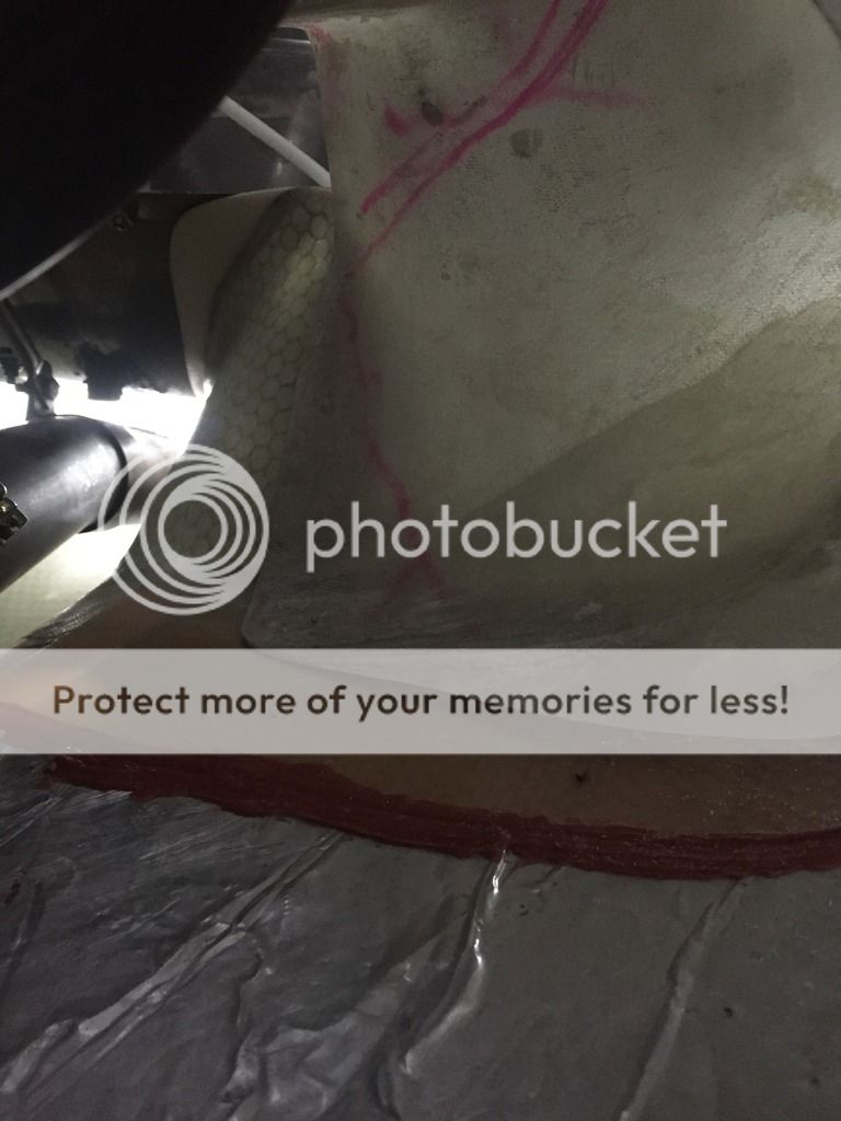
Thanks for the water puddle drying in the bottom DanH, makes sense but never seen water pooled there.

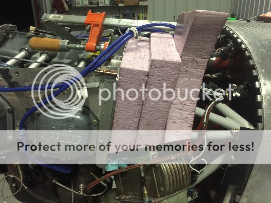
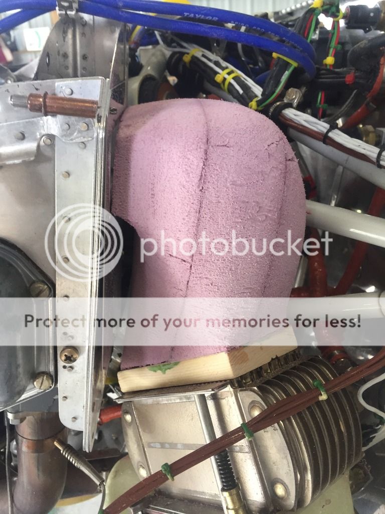
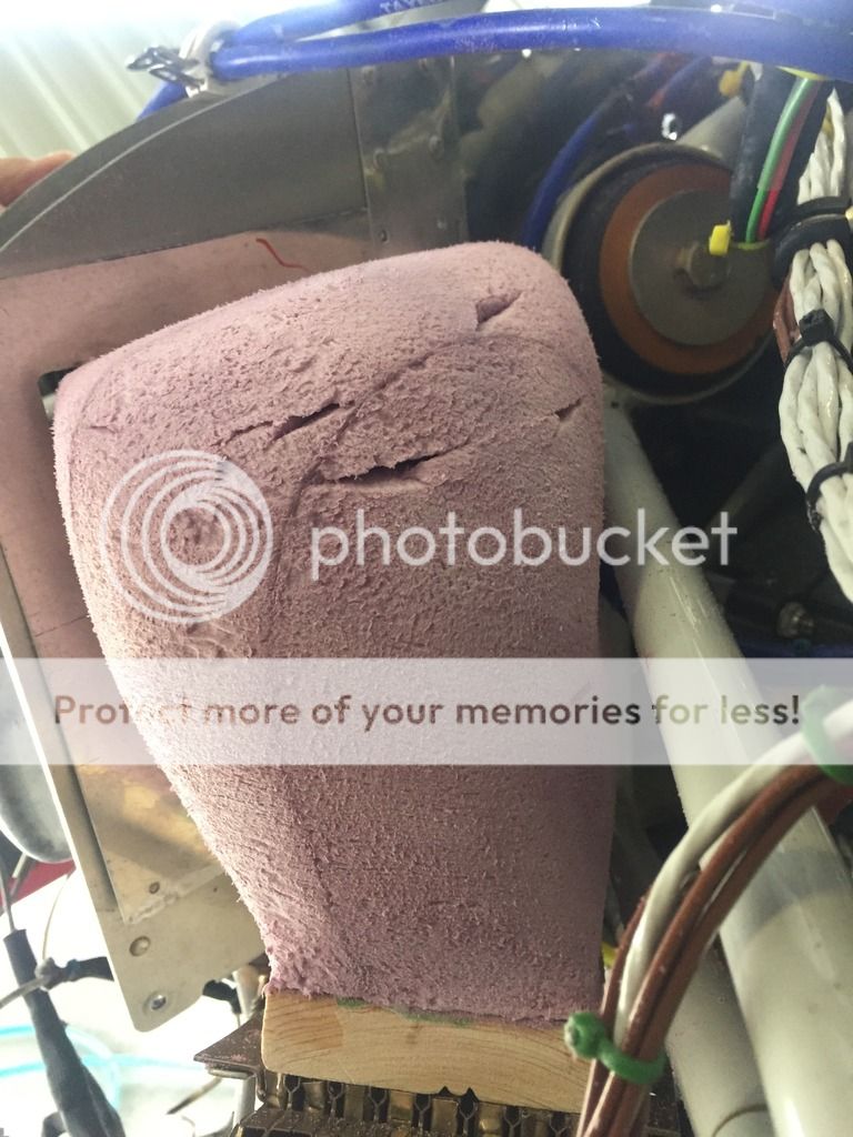
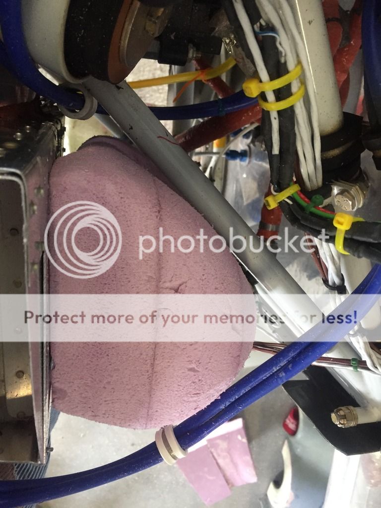
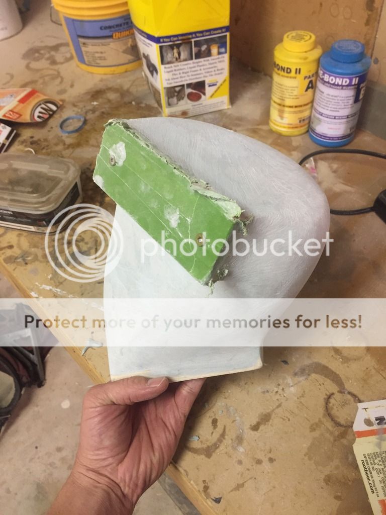
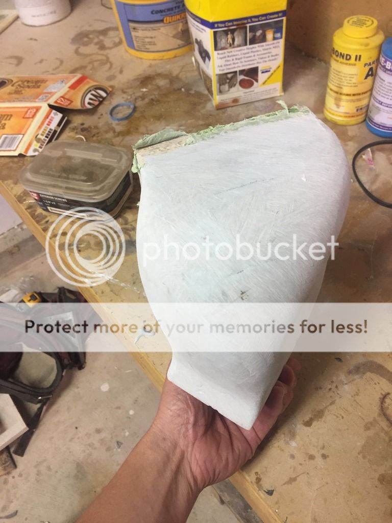
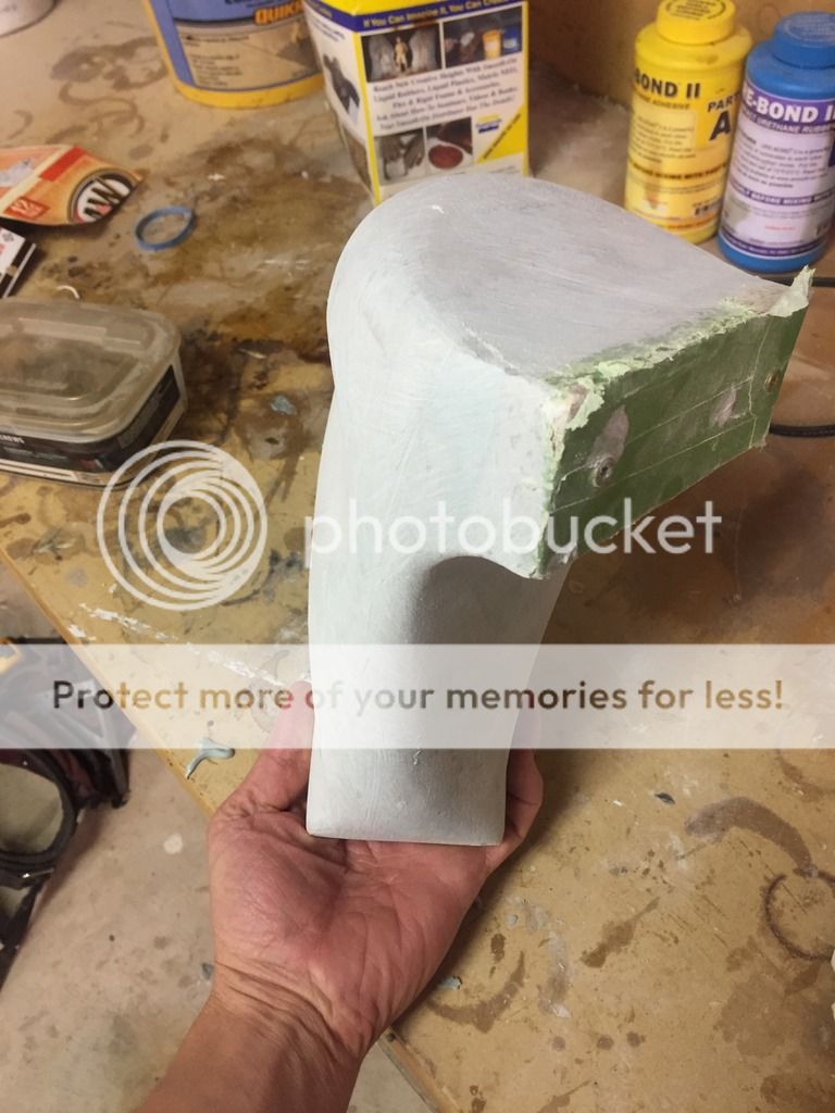
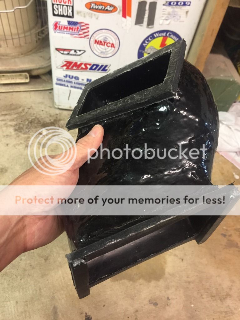
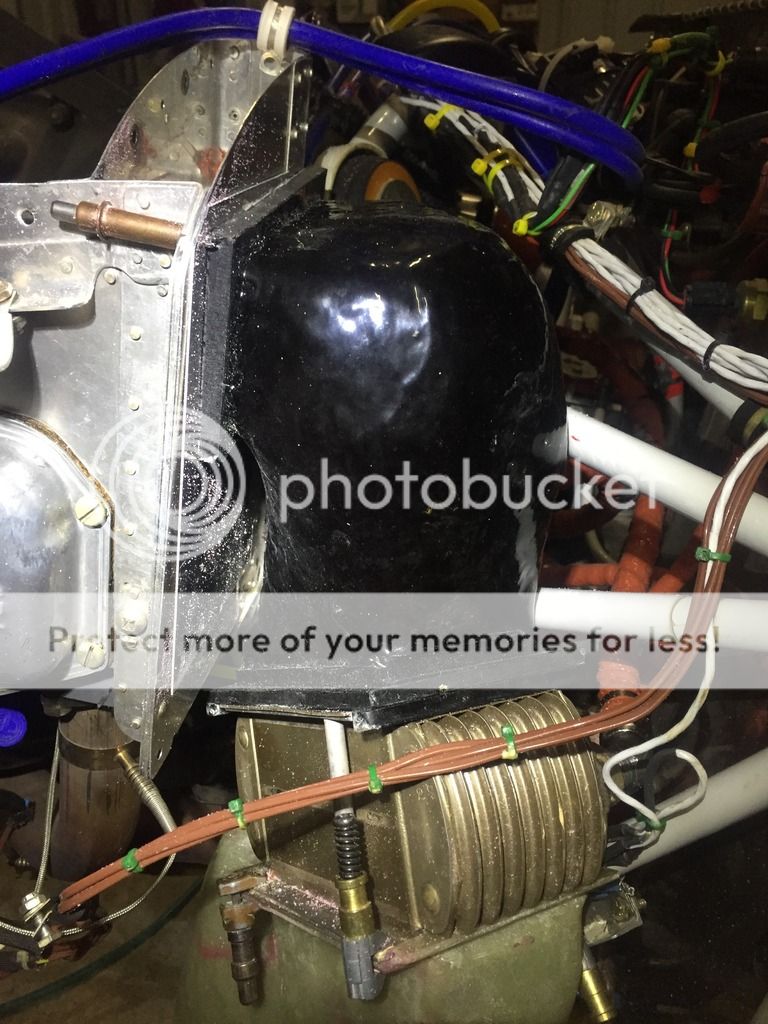
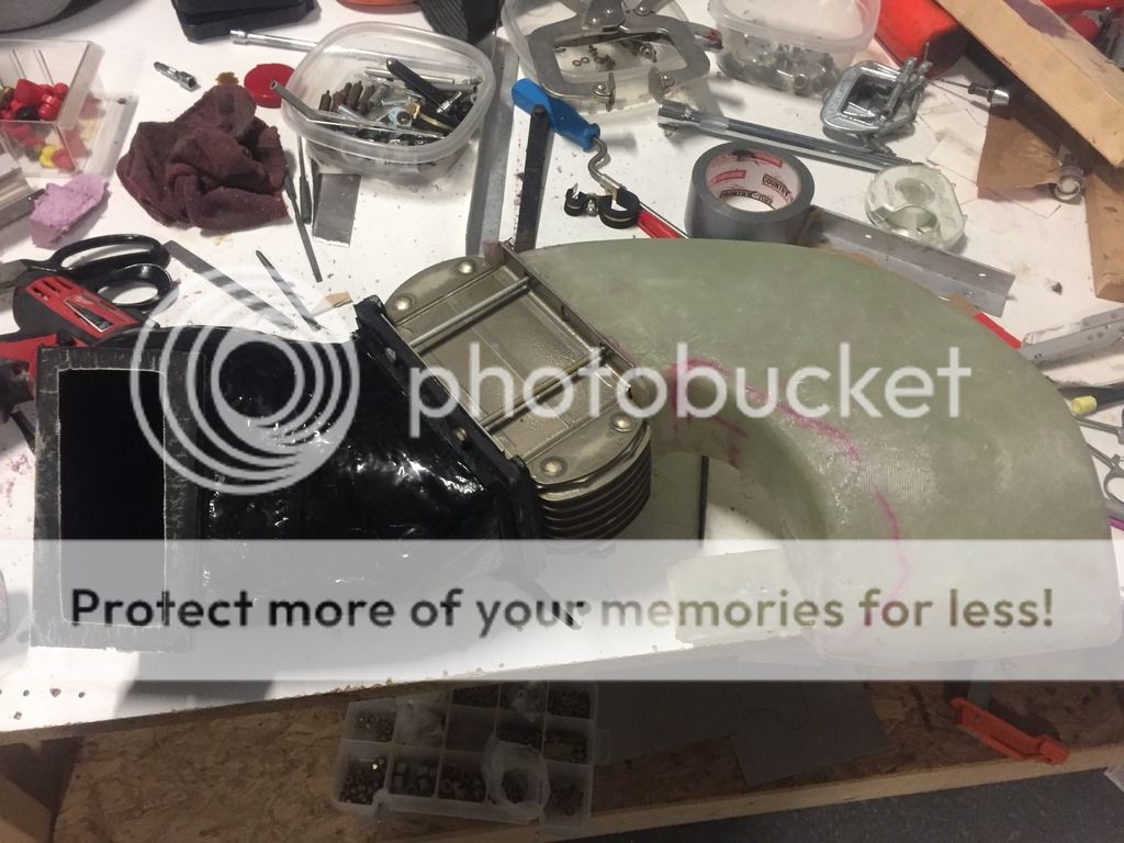
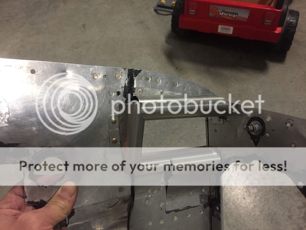
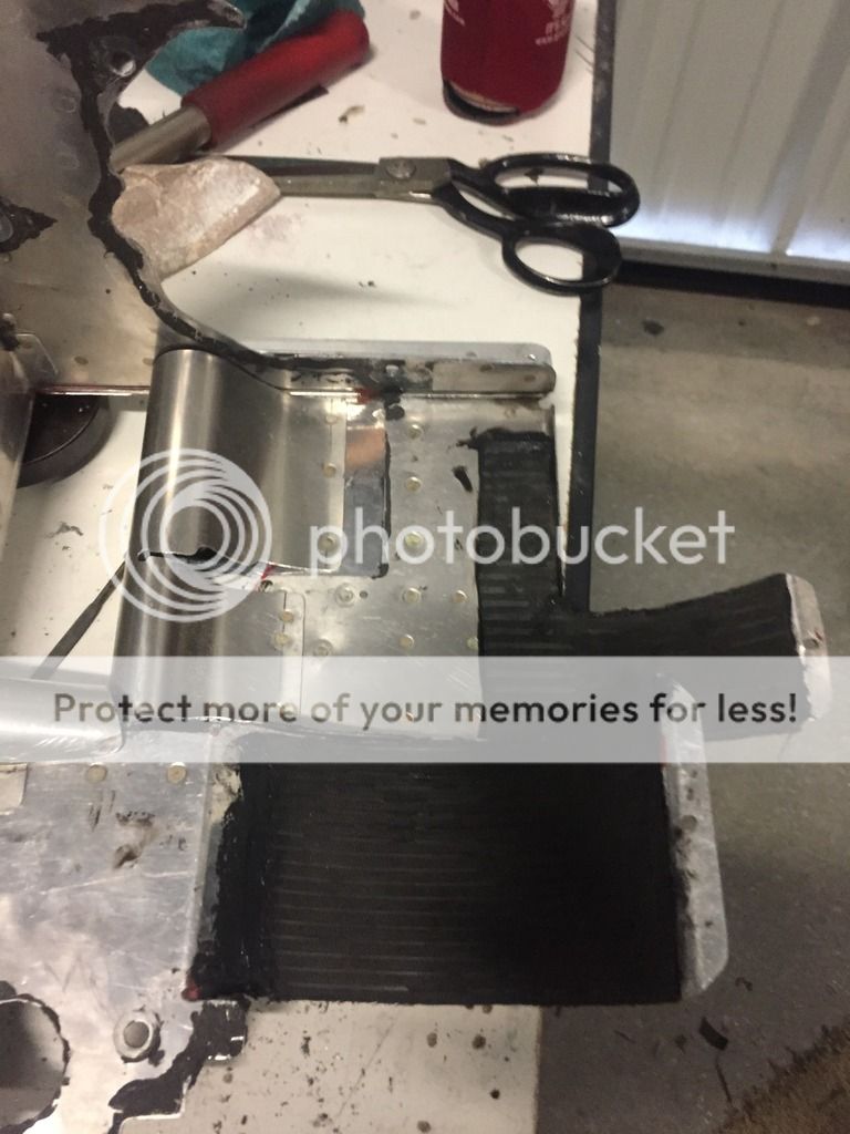
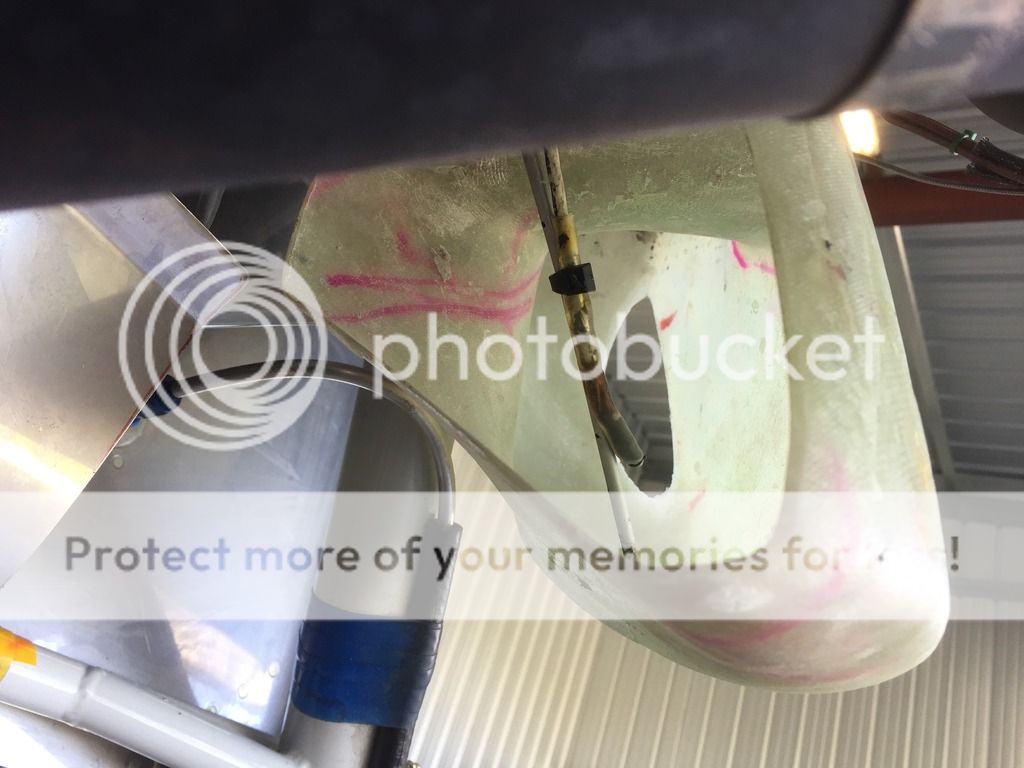
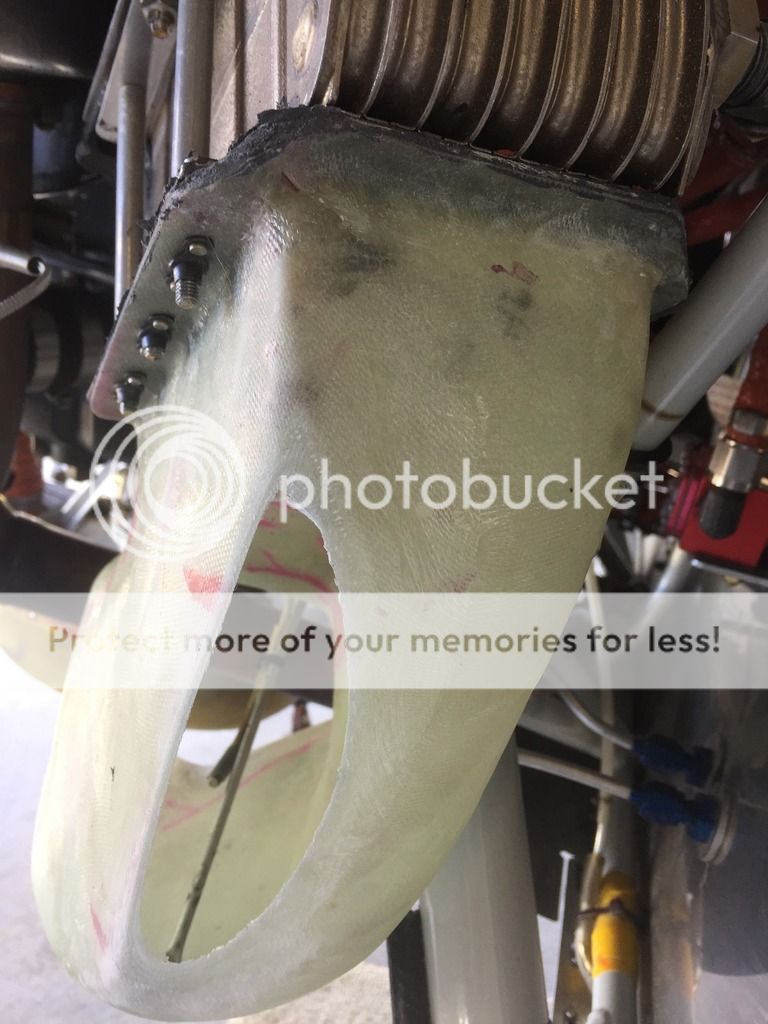
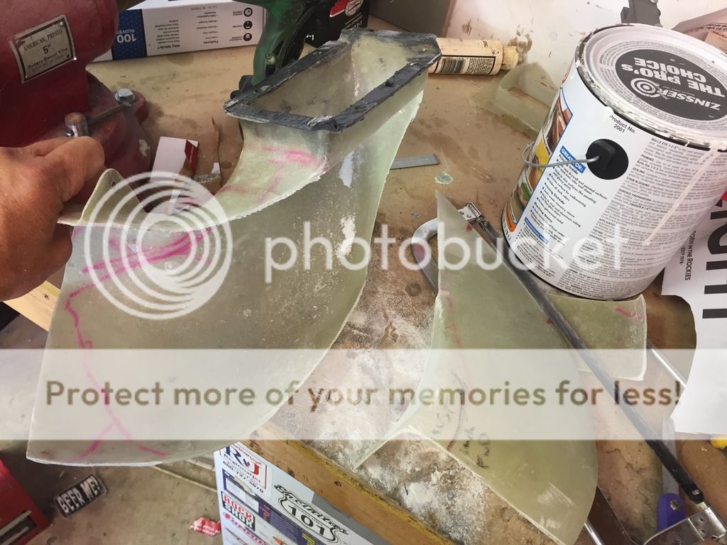
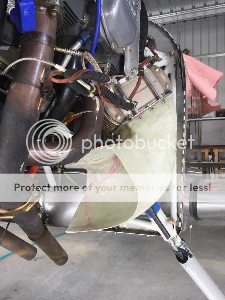
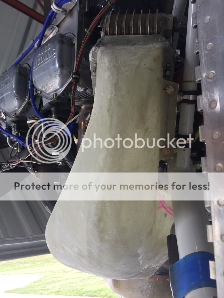
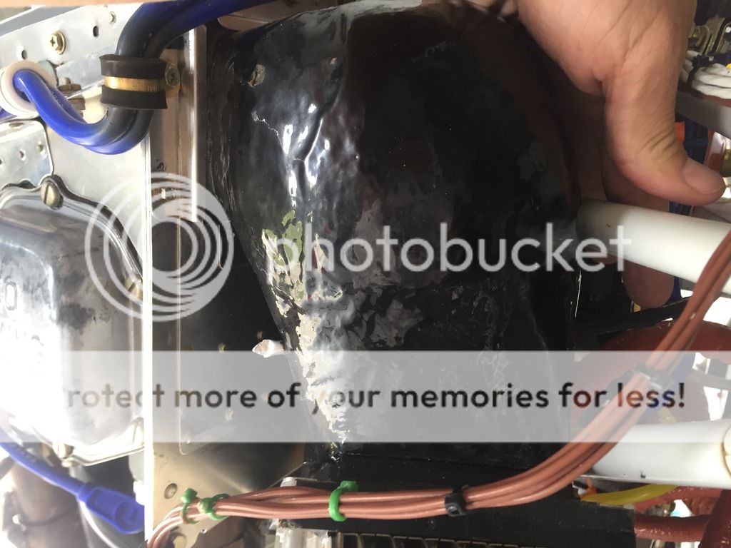
Mark, I'm still wrapping my head around this interior duct although the bluff body is something else to look into. My current oil cooler duct in progress shouldn't affect my CHT's as far as I know, my cowling outlet will remain unchanged for now so lower cowling pressures should remain the same. The interior oil cooler duct outlet pressure reference lower cowling pressure may take some tweaking to get oil temps where I want, we'll see.
I'm also trying to keep cowling removal installation simple and easy, just in case I ever paint this thing.
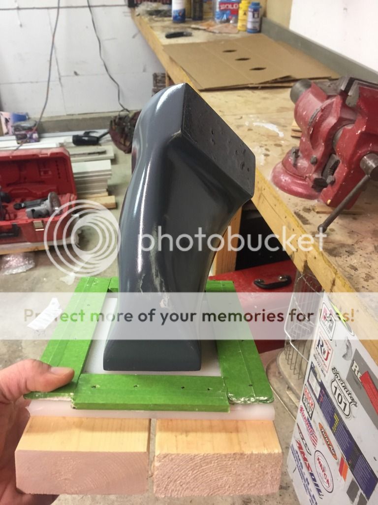
Part of what is driving me is the reduced cowling exit area some people have achieved. My cowling exit has been fixed at about 35 sq inches and working well the past 60 hours or so, I was amazed a few curves allowed me to keep the same cooling with a smaller exit and 2 extra knots!
 
I'll do the water test but I'm pretty sure you're right.

I used some cardboard scraps and paint stir sticks to position some flanges on the duct, I used the DanH fiberglass method of wetting the glass between 2 sheets of plastic and squeegee'ing out the extra. I did slightly wet the surface of the duct wth epoxy before putting the glass on.

E259117F-5BA2-473A-80F1-77EA908B41AF_zpskna8uhrl.jpg


2B31AE30-A796-437B-85B8-542B2C7ECD17_zpsvlfryxsu.jpg


Kinda hard to position the duct so gravity helped hold both flanges on at the same time, I plan on doubling up the flanges from the opposite side once the first side is cured so it has glass from 2 directions holding it to the duct.

134D3D8D-9FB7-4DF6-9047-AB38AFD5AA02_zpsycccaycx.jpg


6D833FF5-494C-401E-B19D-EC7C8FDFBD3A_zpscdnnxbqg.jpg
 
With the lower duct and cooler clamped in place I found it easiest to cut the individual piece of foam to fit and them glue them together with epoxy/micro.

F90A8B4D-CD49-4542-BC30-D8C29F4D905B_zpsy5ofgs44.jpg


The foam sanded to shape, I tried to expand everthing aft of the opening. It does get tight and small around the engine mount.

A946F286-8E36-4A40-B158-1EE94C55940D_zpsprsxcpss.jpg


719E6B18-2333-4E3D-A048-25497093E044_zpsineytq8n.jpg


15EB9B99-C8B8-440B-A269-FA5A4EDF9C0A_zpsnmutamng.jpg


4-5 layers of filler sanded down to make a smooth surface, ready to check the fit again.

62A0B38C-58F4-4338-9E87-9D4195FE7F2A_zpsj71fxga6.jpg


930448EE-19D8-4355-9321-4A529C348A63_zps3kijlff9.jpg


The narrow corner where the engine mount converges with the baffling.

DCAFE445-A969-4EBD-99FD-E50B005A6F9C_zpsdys3wdr6.jpg
 
Last edited:
Clean

Andy,
Awesome work.
The pictures make your shop look like an operating room.
When I do that kind of work....well, lets just say it is a mess!
Thanks for sharing.
 
Bruce,
I ocassionally enjoy a Tank7 but hard to beat a Blvd Pale!

Bob,
My shop and handiwork are way worse in person, both a work in progress.

I do try to do most cutting and sanding outside, over a trashcan or next to a shop vac to minimize the mess. I also generally spend 30 minutes or so tidying up around the garage before composite work. I've got to have separate space for cutting cloth off the roll/mixing epoxy/wetting out cloth and everything else needed within easy reach.
My larger/complex layups end up being kinda a "date night." I want everything laid out and prepped ahead of time with an open time frame with twice as much time needed available. Sometimes I have to plan/wait a week or so for the right timeframe but it helps to only be limited by the epoxy working time.
 
I made a base to mold the flange out of a plastic Wal-Mart cutting board, I cut up an old yard stick and covered it in waxed tape for the sides of the mold. I used scrap 2X4's under the base because the shortest finish nails I had to tack everything together were 2 inches. Mold waxed and PVA'd and screwed to the base and ready for some rubber.

C992454D-F461-433B-9725-76A5AF3E9A82_zpsgq8idhp1.jpg


I used a lot of cabosil in the first 2 coats of rubber (Smooth-On PMC780 Dry) to keep it from running off the mold, It left a pretty rough surface brushing it on.

CF1FBBE2-53C2-4089-BB24-498AC732E598_zpso5aydsni.jpg


2 Thick coats of rubber followed by a thinner coat with less cabosil covered by approximately 3 inch wide strips of rubber infused fiberglass. I initially attempted a 1 piece pattern, but was concerned about accurately placing the wet cloth on the plug with 2 flanges and decided to piece it in. I should've used the plain weave fiberglass, the E glass cloth was hard to get the airbubbles out of. The bottom flange was filled with un-thickened rubber after I applied the cloth to the mold.

58E9E545-D3D9-4BBA-BA82-50C2CE206389_zpsrkpjhi87.jpg


915B8127-660E-46F9-835C-9F3163732818_zpsitoi0syj.jpg


I nailed strips of the cutting board over the partially cured flange on the bottom and tipped the plug over to mold the flange on the top side and added another coat of rubber over the E-Glass. I decided to try the layup schedule this way so I could incorporate both flanges without having to glue a flange on later and worrying about the joint coming apart. I'm kinda thinking the lower portion of the top flange is going to be more of a thick lip than flange, not enough room between the flange and body of the duct. I may have to think of another way to attatch the top of the duct to the baffling, we'll see in 48 hours.

F1F768EE-93B9-42E6-BA3F-78AA1A0BA466_zpsonsjffsu.jpg
 
Last edited:
Popped the mold and styrofoam out and trimmed it up slightly. The lower flange near my thumb is pretty much non-existent, the flange and body of the duct pretty much just joined together. I should've put a little more curve in it and made the flange longer.

ADBAD60A-5FD1-4132-A301-388882D7088B_zps6usmcyzn.jpg


Fits really well in position on the cooler/baffles. The flange for the oil cooler works well, I'm gonna have to rethink the flange by the baffling.

4AA4F18E-2B81-4BA5-BE46-EAAED5571CA6_zpsrgilb9ll.jpg
 
Andy, maybe you have enough at the narrow flange to catch it with a Z-bend, then bolt through the other three flanges?

 
Dan,
That was kinda my original plan and might still work if I remove a bit of the rubber, I have plenty of thickness. Problem is removing the rubber, this stuff is tuff!

I think a little time with a small file/sandpaper and some blisters will yield a usable flange to utilize a z bend. I used a .063 ruler covered in tape to mold a flange, I just didn't push it far enough into the mold. I probably should've made the flange thinner as well. You can see the tape covered ruler in this pic sticking out on the sides of the flange.

F1F768EE-93B9-42E6-BA3F-78AA1A0BA466_zpsonsjffsu.jpg


On the plus side the duct-cooler-duct connection interfaces really well. I'm thinking of using the long bolts and spacer tubes between the flanges of the cooler to discourage any bending of the oil cooler flanges and fabricate a metal bracket over top of the rubber duct-cooler bolts to engine mount.

EC3B106D-DD36-4CDB-B361-A26C25861F6E_zpsk4ddlksx.jpg
 
Last edited:
I'm really kicking myself for the workmanship on the upper flange. I was hurrying to finish it up before work and it was off square and not quite big enough. Enough about the lemons the new flanges are the lemonade. My harbor freight bending brake does OK, but I need a larger selection of clamping blocks and strips especially for these narrow bends. I made the small bend first, than clamped my bracket on the outer side of the brake and used a bucking bar and hammer to make the second bend.

62A4026E-0010-4432-B54C-0786DFF99D69_zps3jseq1hr.jpg


AFEB0536-6558-4899-B335-4864EA7325AF_zpsv9x4egiy.jpg


77A25A5A-AB6E-49DB-A0E0-F65A1A68DBAC_zpsoeqqtbev.jpg


The urethane rubber doesn't file or sand real well, I had to "machine" out a groove with a box cutter and new blade.

4C8072EA-02C8-4410-BAAD-D93670AA97C0_zpsdp6xbdq9.jpg


It fits pretty well on the baffling.

9D1F24C8-5C32-44B0-8C08-67A04BD2CF88_zpsynbmqc0d.jpg
 
I made Z-Brackets for the other sides of the flanges.

91B17F7C-D6F6-4F14-8728-A8E6EA1BBF17_zpse44luitw.jpg


D2E6C952-C3FE-4A0C-9384-940ABBFEE324_zpsuzl3694k.jpg


I never liked the offset joint in the baffling by the head/cylinder junction and made a upper brace. I think with the plenum I can now forgo the angle brace from the engine to the baffling. It took some thinking on the riveting sequence along with some blind rivets to Rivet it all together.

EA329E17-C196-4EE7-A660-CD01F103924E_zpslvcatfh8.jpg


D888C45E-EC38-4E56-B825-BC828EB7D628_zpsmtr47cbq.jpg


B9C11A4B-E6F1-47E8-8190-5BE9BF5D8EB2_zpsev2yrssl.jpg


I RTV'd the old cylinder wraps to the baffling, on my other cylinders it doesn't seem to affect cooling and keeps the cylinder fins from eating the baffling.

AF23CDF2-A604-43E6-BD0A-F87B5B3AC0E0_zpsu2ogoifr.jpg
 
Last edited:
I installed the rear baffling piece and RTV'd the Oil Cooler Boot to the baffling. The extra bracing around the oil cooler junction left the ol' center case to baffling angle brace unneeded so I removed it. Ultra Black RTV seems to stick to the urethane rubber pretty well and it's a little more flexible than the ureathane specific glue smooth on sells. I also had to re-route the spark plug wires.

63B30EA1-02BC-4FAD-961D-32F263E36122_zpskqhbdz7k.jpg


8A25A942-18B3-46F7-AD67-4787BB9D11AA_zpsrybpdzgo.jpg


I used some packing tape over the oil cooler to provide a slick release surface, and RTV'd a Ultra Black gasket onto the fiberglass duct. It's much easier to make this gasket stuck to 1 part now for future disassembly. With a little more time and clean-up I hope to be test flying within a week and a half.

F76D2431-5088-40E5-8C19-BE4A711F8DF2_zpsorjlsm3z.jpg
 
Last edited:
I finally assembled it all....

EA5C25FC-8BB7-4FAC-BF36-6DF48894CC45_zpszdgxmcmb.jpg


3C2F310D-8B5A-46FD-A909-D154605E5460_zpsjnlv57cg.jpg


Of course it shifted just enough from fabrication to assembly to hit the cowl.

81658A8F-77F0-4B7E-9B70-8933E14B9E3E_zpsyvkxmcdc.jpg


My Lil' Dude helped me sand the corner of the duct off to give a smidge of clearance. Previously he scooted the ladder over to the worktable, grabbed the sanding block with 36 grit and sanded my gear leg fairing......primer has its advantages. I want to test fly the existing duct as is and see what my oil temps are, I can expand/close the duct up later.

F7AEEB48-F1B1-4806-BCAC-C7CBBFB2FE4D_zpstubpwdna.jpg


0FEBC419-BDED-4B08-BDFF-3951BA5CFF6D_zpskx40y82j.jpg


Weather and a hungry Lil' dude called the test run for another day, hopefully soon.
 
Last edited:
Hahaha, QA inspector Lil' Dude also reorganizing the "upper" drawers on the toolbox. At least I used to have a vague idea where things were at.....

CC6A2D89-D6BD-40B0-B0FC-1AA6D5ADAFF5_zpse8zdapf2.jpg
 
Ground run and subsequent test flight went well. The boot does transmit quite a bit of vibration to the oil cooler and the fiberglass duct at idle, above 1000RPM it barely moves. Part of me thinks I should re-design the boot to be more flexible, part of me thinks it doesn't shake any more than the standard oil cooler location/baffle material/fiberglass airbox. My guess at any failure points would be the adel clamp mounts to fiberglass duct attach points which isn't a safety of flight issue. I plan on more flight time and keeping a close eye on it.

My initial observation shows a definite improvement in cylinder #4 CHT's, as noted before it's my leanest cylinder at full throttle CHT was 15-20 degrees hotter now closely matches #3 in CHT. Oil Temps seemed to be 5-10 degrees cooler. More flight time is needed to get defenite temps.

After de-cowling and inspecting everything I installed a temp and pressure probe into the oil cooler exit duct to gather temps and pressures, I didn't want to be distracted with anything but flying and engine gauges for the first flight. I have a pair of piccolo tubes above the cylinders in the upper plenum, below the cylinders for lower cowling pressure and now a pressure piccolo in the oil cooler duct. I haven't been able to measure any pressure difference in the lower cowling under the cylinders compared to several locations around the firewall. I'm curious if I have extra pressure differential to play with between the oil cooler duct and the lower cowling. If you recall I have a sizeable hole in the oil cooler duct so it doesn't hit the cowling.

225C0028-26DB-478B-859F-B3C3CEB79DA1_zpsnyphkxgr.jpg


I have three ports on the firewall and three tubes with different colored tape denoting upper, lower and random piccolo tubes.

68C89679-1EA1-41BC-BD72-279C1C9B54B8_zps9xmvpdca.jpg


Tubes and manometer in the airplane along with the voltmeter to read temp.

D1D0F145-26CD-402A-B684-6E5A1851BF85_zpsu3hjeqgu.jpg
 
Nice

Great work Andy.
I feel like I am cheating on a test while watching you experiment.
Thanks for the wonderful thoughts and pictures.
 
Keep swinging Andy! You're doing fine.

Ground run and subsequent test flight went well. The boot does transmit quite a bit of vibration to the oil cooler and the fiberglass duct at idle, above 1000RPM it barely moves.

Remember, your eyes can't see vibratory movement higher than a certain frequency. It's a lot like not being able to see the flicker due to 60 hz AC.

I have an adjustable-rate strobe for looking at vibrating objects. Tuning a strobe to the exact frequency of movement freezes the object so it appears motionless. Tuning just a bit higher or lower puts the vibration in apparent slow motion, allowing visual observation of the entire vibratory cycle or repeating motion.

I have seen propeller blades twisting torsionally as they rotate. I have seen the center of a control pushrod describe a circle about 3" dia at one particular engine RPM; it appeared perfectly still when I released the strobe trigger. I have watched the sides of a fuselage pump like the gills of a fish under the influence of propeller inflow (it was a pusher). And I've watched an entire engine move through its vibratory cycle on the mounts...and it appeared motionless without the strobe.

Point is, although your "no relative motion" observation is probably correct, don't bet on it if failure has a consequence. Put another way, seeing is believing, but your eyes can lie.

Part of me thinks I should re-design the boot to be more flexible, part of me thinks it doesn't shake any more than the standard oil cooler location/baffle material/fiberglass airbox. My guess at any failure points would be the adel clamp mounts to fiberglass duct attach points which isn't a safety of flight issue. I plan on more flight time and keeping a close eye on it.

Works for me.

I haven't been able to measure any pressure difference in the lower cowling under the cylinders compared to several locations around the firewall.

There's no reason to believe you'll find a pressure variation between any two points inside the lower cowl volume.
 
Several tanks of fuel later, #4 cylinder dropped 15* and is now right in line with #3 in climb and all cylinders in cruise. Oil temp is close to the same, the lower duct was consistently showing .25 inch H2O less pressure than the lower cowling at cruise speeds. No speed difference was found, structurally everything as installed.

One difference noted, oil temp increases with a power reduction and increased airspeed in descents. I need to measure the upper face of the oil cooler and see how it compares to upper plenum pressure.

I modified the lower duct from mostly constant area to an expanding duct, I sliced off a portion of the duct leaving the attatchment and cowling/engine mount interference points.

F24F8515-3D4A-4CA2-ABF4-00D791F95644_zpsu0hyiuca.jpg


There's a Smooth On dealer a couple blocks from work, I grabbed a sample pack of their 3lb density pour foam.

18941AB5-4813-48AE-B837-16180768B8C6_zpscchitsts.jpg


I tapped some damns on my duct and used chunks of pink foam as a "bulk filler." If you use "bulk filler" make sure it is stuck in place, mine wasn't and the pour foam floated the chunks of pink foam to the top as it expanded and I had to do a second pour.

539B427C-F98E-4917-8B7C-019995D4A611_zpswm5reasc.jpg


I attempted to make the new lower duct a divergent duct to see if I could increase the pressure differential across the oil cooler.

2F34986E-AE16-43B3-B884-B49213801BFF_zps1wjbbbth.jpg


D50FAA98-C5F2-4933-9ECF-955F6B44F406_zpsewcfju62.jpg


BA2CAE16-86EA-45D4-9B7D-EADC61D92148_zps8gztb1kp.jpg
 
New lower oil cooler duct installed.

CA2058F1-ECC9-4F8C-83FC-2FE3F60F5A2B_zpswffhwxff.jpg


FDA9862A-7C7F-4836-BCE9-908D2B85219A_zpsqkmfkcjy.jpg


The junction of the oil cooler duct and lower cowling.

39C3D9EA-81EF-4778-9673-5C14DD3BA669_zpsx8wo8gu6.jpg


I installed a piccolo tube in the upper oil cooler duct so I can measure the pressure on the front side of the oil cooler.

530E8433-0014-4972-9040-0F7971C08D39_zpsv1cgxb31.jpg
 
It's been a while....
AnyWho, I've got a litter of older Odyssey PC680's littering my hangar shelves. Seems after 1 year they fail to start the airplane, take a correct charge etc. I've put in various old Pc680's sitting on my hangar shelf 3 times now and it starts the airplane decent. Granted the old battery now starting by RV was removed several years ago because it wouldn't start my RV. I generally fly 3 times a month minimum and (I don't use a tender) only used an Odyssey charger when needed, which seems to be right about a year. Hard to trust an older battery once removed for not starting the airplane for Xcountry trips.
So I did some reading and bought an ETX680 EarthX Battery, why buy their pre-made battery box when I can make one for $4/hour minus materials I already have....
I recieved the EarthX in the mail today, really is hard to believe the weight difference with it and the PC680 in the other hand.
I made a paper pattern to hopefully figure out any mistakes first, it was also way warmer in the kitchen than the garage.

IMG_8286-L.jpg


Cut some .063 oversize and started bending things with my el' cheapo brake...

IMG_8292-L.jpg


Checking the fit on the battery, the bend radius can vary and change dimensions a lot if you're not careful.

IMG_8293-L.jpg


More Bending and Fitting....

IMG_8294-L.jpg


IMG_8296-L.jpg


IMG_8298-L.jpg


IMG_8299-L.jpg
 
Last edited:
I used 2X4's along with a scrap chunk of 2X4 and a hammer to bend the smaller lower flanges, I pre-plan the bending as much as possible but on multiple bends you usually have to compromise.

IMG_8300-L.jpg


By bending the side flanges first I was able to use the brake to bend the longer lower flange.

IMG_8305-L.jpg


I really liked the idea of no hardware to loosen/tighten/loose in the lower cowl to bolt the battery in place so I'm trying to copy the retention flange EarthX has on their battery boxes.

IMG_8302-L.jpg


IMG_8303-L.jpg


IMG_8304-L.jpg
 
Last edited:
The bendable retention flange wasn't so bendable, I ended up using a couple small angles on the side of the box and little tabs as hold downs. After lots of holes it weighed 6.9 oz , I'm curious if the one EarthX sells is .032 material.

IMG_8306-L.jpg


IMG_8307-L.jpg


IMG_8317-L.jpg
 
Yes, Overvoltage protection via PlanePower Alt and B&C SD8/crowbar module. I also reset the voltage parameters/alerts in th G3X as suggested in the EarthX manual. I’ve hooked up the fault wire to a discrete input, need to call Steinair for verification on wiring.
I do have a bit of concerne about an Overvoltage from the plane power also shutting down the EarthX via the BMS, my SD8 powers my EBUS fine in cruise but lacks the necessary amps below about 1800 RPM. At some point I’ll become a glider in order to land.

I also received a pm about adding a heat shield on the bottom to prevent heat from the exhaust warping the bottom of the battery.
 
Last edited:
Yes, Overvoltage protection via PlanePower Alt and B&C SD8/crowbar module. I also reset the voltage parameters/alerts in th G3X as suggested in the EarthX manual. I?ve hooked up the fault wire to a discrete input, need to call Steinair for verification on wiring.
I do have a bit of concerne about an Overvoltage from the plane power also shutting down the EarthX via the BMS, my SD8 powers my EBUS fine in cruise but lacks the necessary amps below about 1800 RPM. At some point I?ll become a glider in order to land.

I also received a pm about adding a heat shield on the bottom to prevent heat from the exhaust warping the bottom of the battery.

Hi Crabandy,

Please note, the over voltage protection on the Plane Power is for the alternator to be shut down. The battery would continue to work and run the EBUS until you deplete all the energy in the battery, same as a lead acid battery. For example, the ETX680 has 12.4Ah of energy. If your over voltage protection is activated due to a failed regulator, you are then on battery power only to operate your equipment. If you use 12 amps an hour, you need to find a place to land in an hours time. If you use 24 amps an hour, you need to find a place to land in a 1/2 hour. Hope this clarifies things.

Hi Kathy, I believe I just spoke to you on the phone about chargers for my EarthX. Thanks for answering all my questions!
I understand the battery is designed to provide power as rated after an Overvoltage event, it is a new system added to the airplane and thinking through Murphy?s law. I also have thought through the same senario with my lead acid battery. I really can?t wait to hit the starter button with my new EarthX!
 
Hooking up the EarthX fault wire couldn't have been easier thanks to their excellent manual. 1 wire to a discreet input into the G3X, I temporarily grounded the wire to test the annunciation as it doesn't display if there isn't a fault. Note the red "BATT FAULT" in addition to other alarms on the PFD:

IMG_8325-L.jpg
 
Bend Raidus

Just looking at the bend radius looks a little tight, don't have my old books but thought it was 3 times the thickness of the metal. Also edge of the metal looks rough which can cause a crack at the bend. Just a thought.
 
Andy,

Your thread gives me hope of doing this some day. Love the tech in your plane, and the detail you shared through your building process. Darn you, Photobucket!

I hope Pie is doing well. As a father of 2 under the age of 3 reading about her diagnosis and hospital stay was gut-wrenching.
 
EarthX Battery Life

As posted earlier I gave up on the odyssey battery after 6-7 of them failed at 10-12 months. My EarthX I installed Feb of 2018 failed me today, a smidge over 4 years later Feb of 2022.
I did notice the last 6 months the airplane cranked slower, I wasn’t too surprised when it would only throw 1 blade and stop this morning. To be fair the one blade and stop was very typical of the 6 month old odyssey battery in the winter. After a couple failed start attempts with the EarthX I was able to preheat the 40 degree engine and found a friend with a lithium charger. The charger ran through a complete cycle on the battery in about 45 seconds. Charging and preheating did the trick and I was able to get it started and fly home with the “batt fault” showing on the EFISS and normal charging on both Alts. Back at home and thoroughly warm the airplane cranked well.
I did run the airplane 1 year with the EarthX before adding my oil door cowl flap to aid in cooling, the Odyssey doesn’t let you know it’s unhappy with temps but the EarthX does. Prior to the oil door cowl flap I would almost always get over temp alarms on from the EarthX during summertime quick turns, a combo of hot/cowling mods/starting/charging/slower climb speeds. The oil door flap kept the EarthX happy most of the time, I found summertime/mountain altitudes/heavy it would still overtemp.
Granted my EarthX had the benefit of 3 years flying with the oil door cowl flap, but it gave better service during and lasted 4 times longer than the odyssey. Even without shipping that makes it a better value than 4 odyssey batteries.
 
Thanks for your write-up.
I have 2 EarthX, one in the back and one on the firewall.
Flying since November 2021.

I did hear about the heat issue up front so I installed the front one in EarthX's insulated battery box and routed a 1" blast tube from the baffle to the battery. The blast tube is blocked with tape these days as I believe the battery doesn't need -15C air...
Hoping to keep the battery happy and cool in warmer times.
 
Back
Top