
Van's Air Force
You are using an out of date browser. It may not display this or other websites correctly.
You should upgrade or use an alternative browser.
You should upgrade or use an alternative browser.
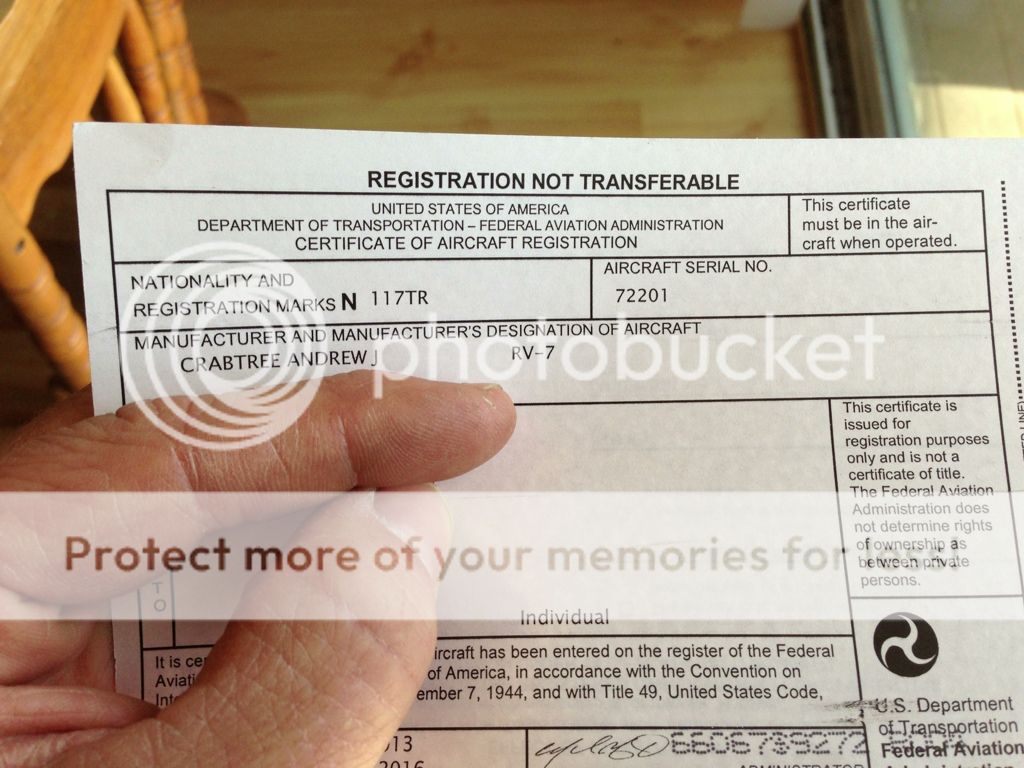
RV-7 N117TR
- Thread starter crabandy
- Start date


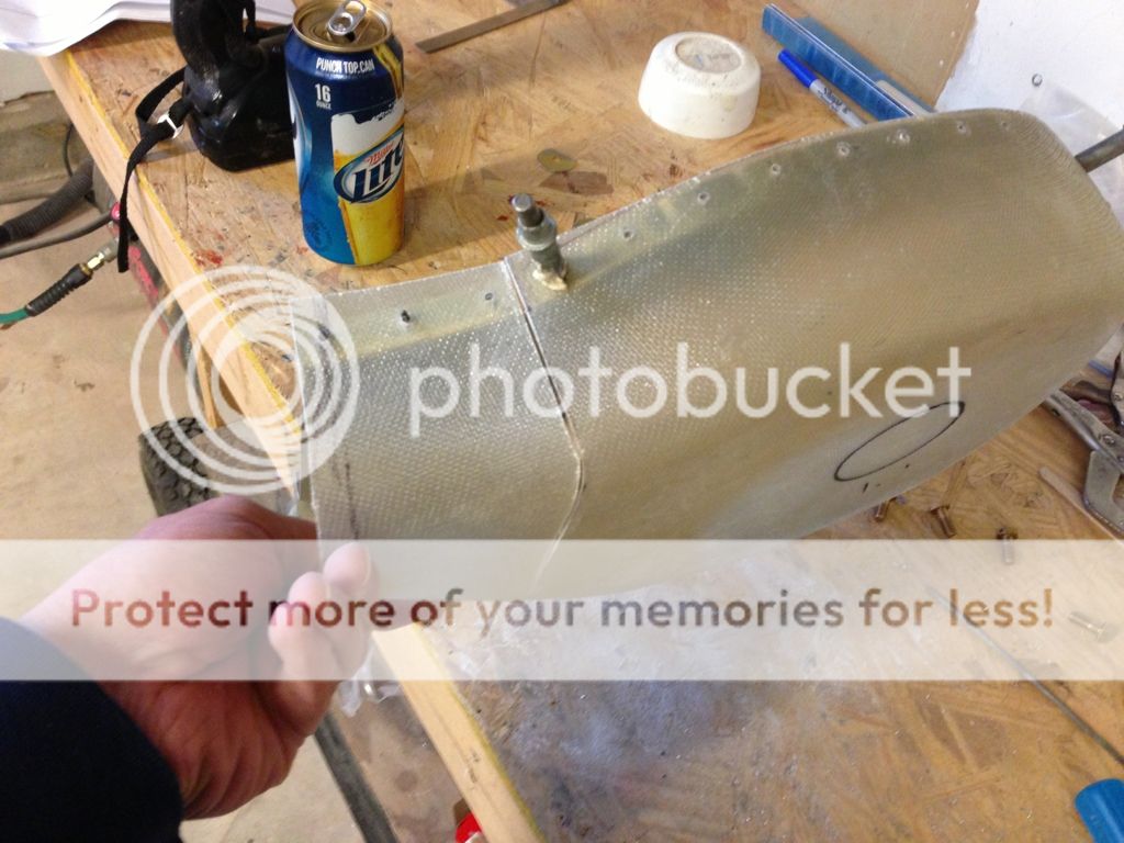
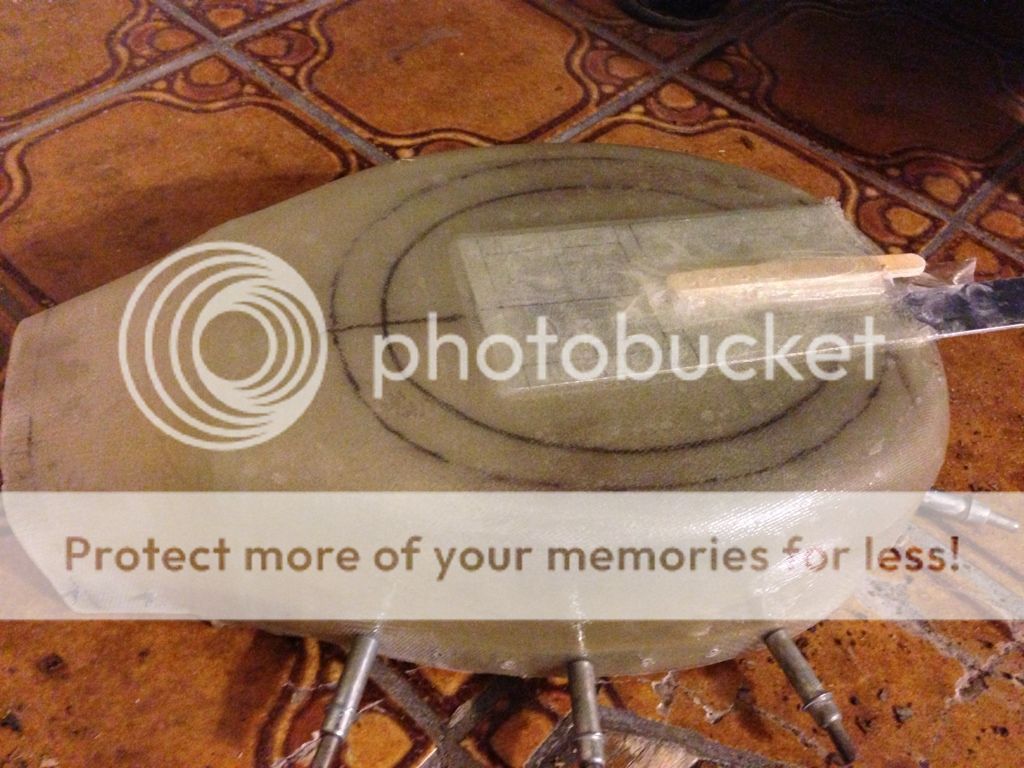
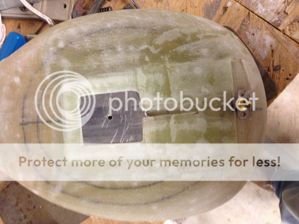
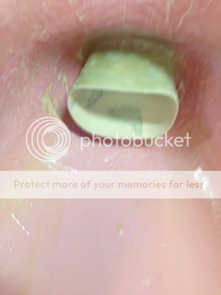
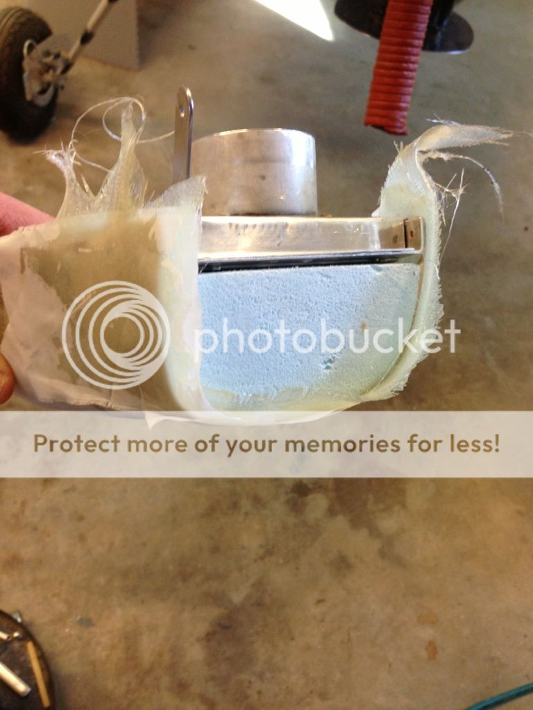
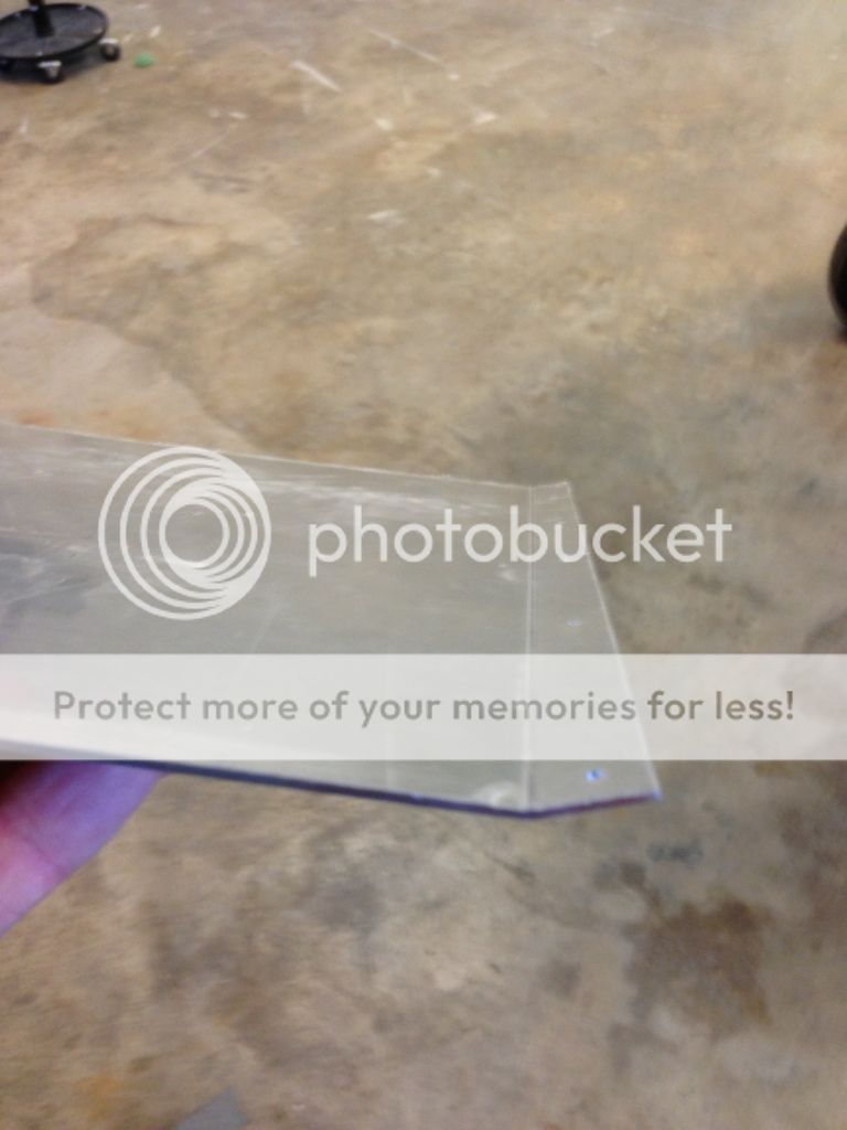
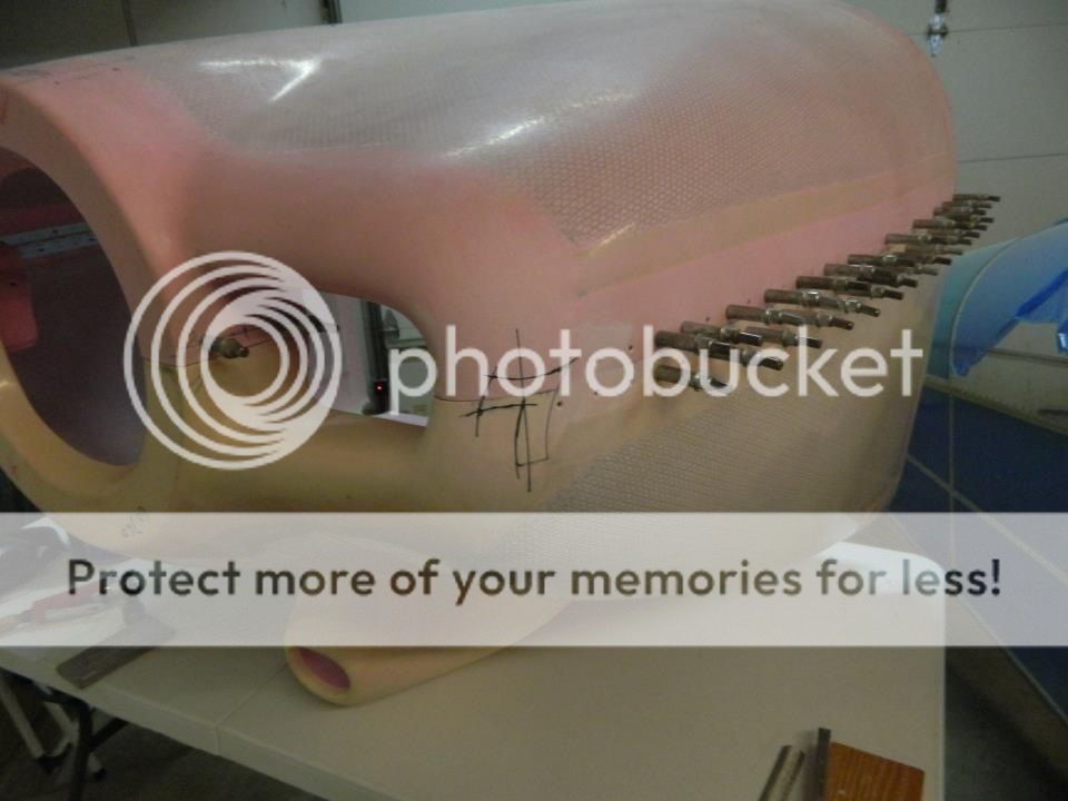
Fiberglassed the scoop back on and decided to try and make my own air bypass. The stock bypass has some bad reviews and you cannot reset without pulling the cowl. I taped up and waxed a piece 3x6x.063 scrap and glassed it to the bottom of the FAB. I added a couple of Popsicle sticks to the center so I could cut out the center for attaching the cable, I left the back open so in theory the .063 will slide right out once its cured. I'll find out tomorrow!
You would think with two little girls there would be a balloon in the house/garage somewhere but had to borrow the lettuce bag.
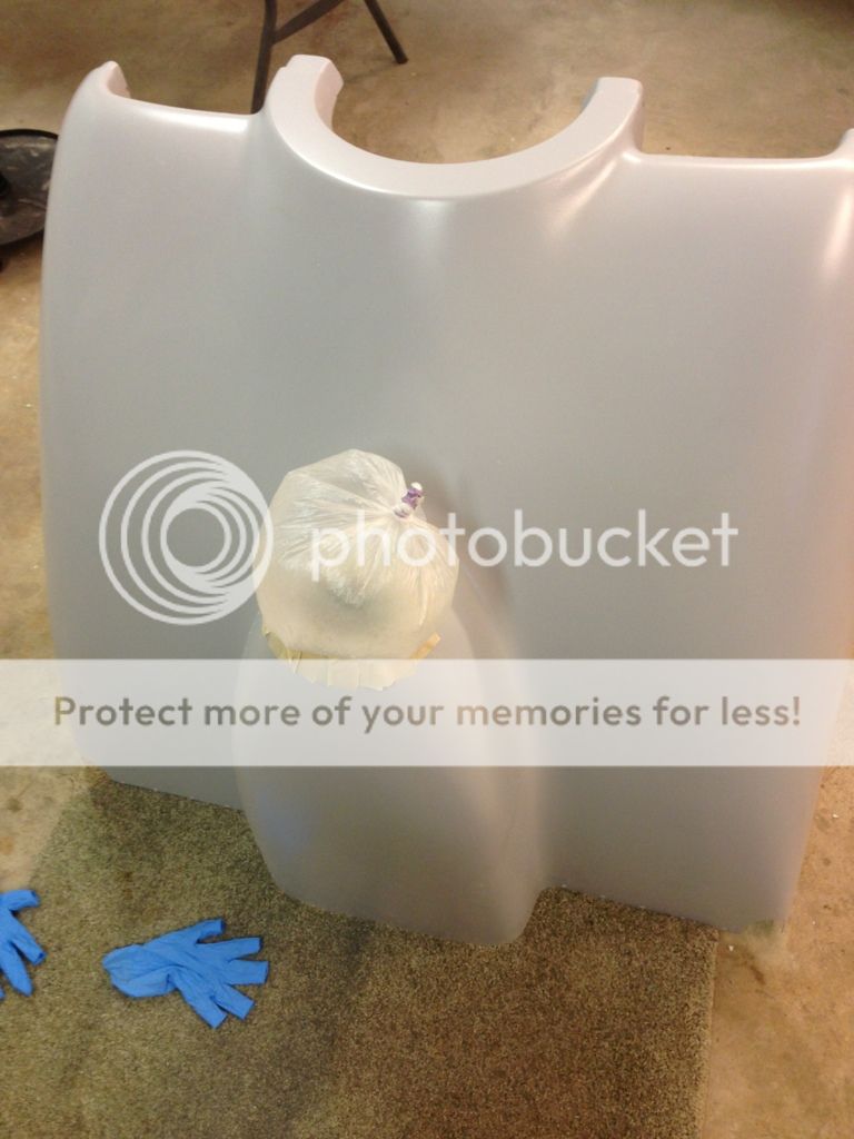
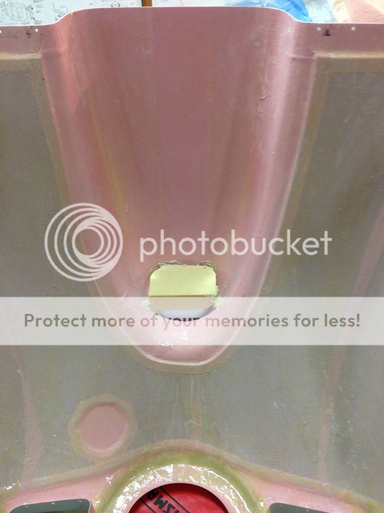
I just put one layer in the first night just in-case it didn't turn out I didn't want to sand multiple layers of glass. Next day it was great, the glass conformed Perfectly to the foam. I bought balloons (per Vans plans) and put 2 more layers of glass in but when I blew up the balloon it required too much pressure to expand and slowly squeezed the fiberglass out of the scoop. Back to the fridge to snag the last veggie bag, green onions. Maybe the "hot dog" shaped balloons would work better than veggie bags, probably smell better than onions too!
Last edited:

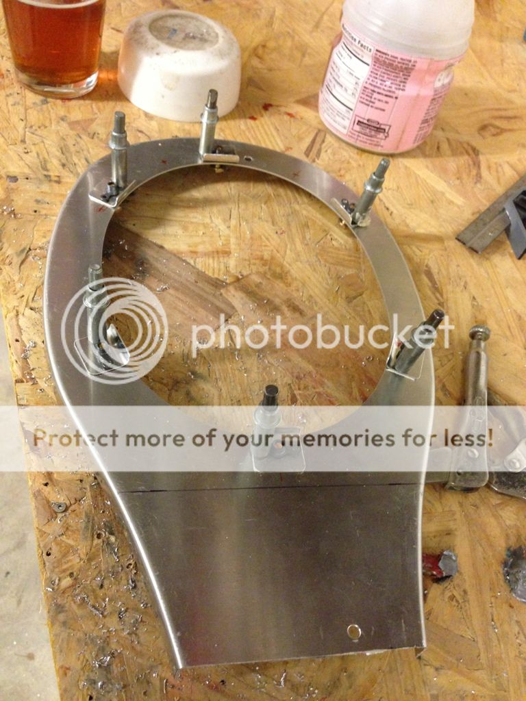
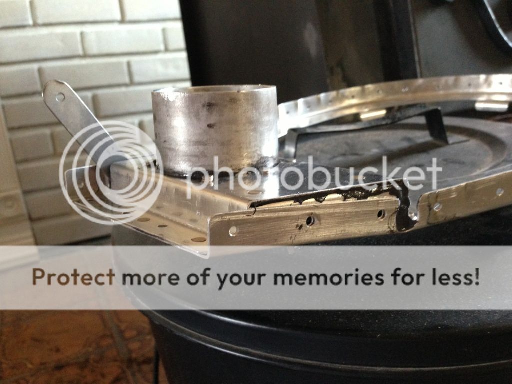
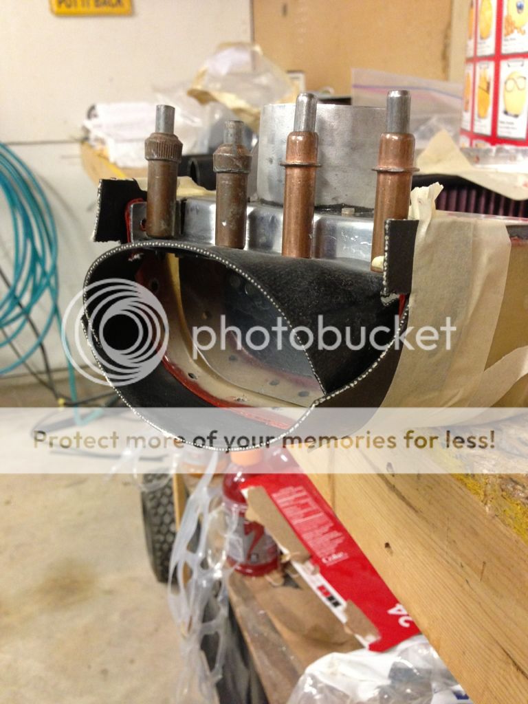
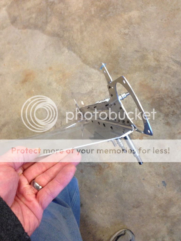
Carb heat flange
I received my heat muff and flange from Robbinswings the other day, unfortunately I had already made the flapper door and there was no way it was going to fit. My carb must sit further foward on the sump than most. 8 hours later I've got my flange fitted...
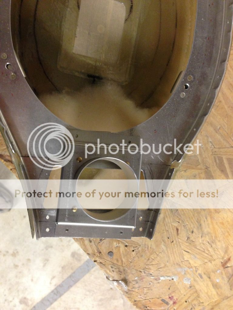
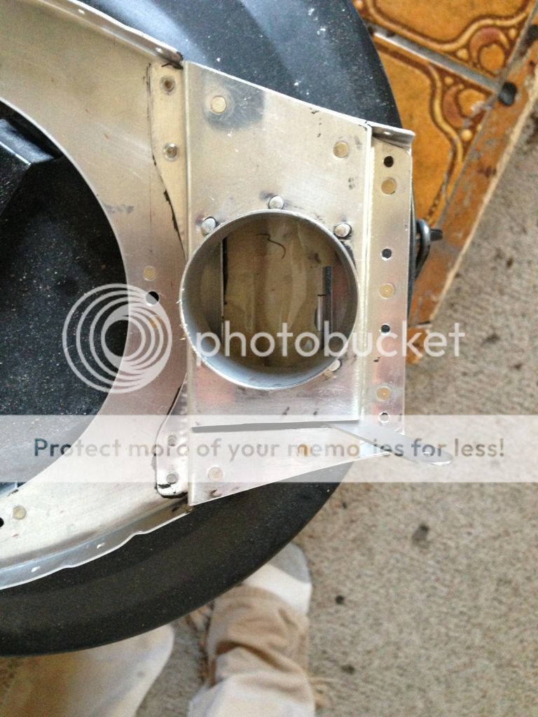
I received my heat muff and flange from Robbinswings the other day, unfortunately I had already made the flapper door and there was no way it was going to fit. My carb must sit further foward on the sump than most. 8 hours later I've got my flange fitted...
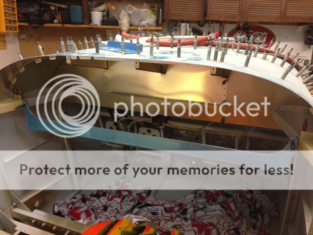
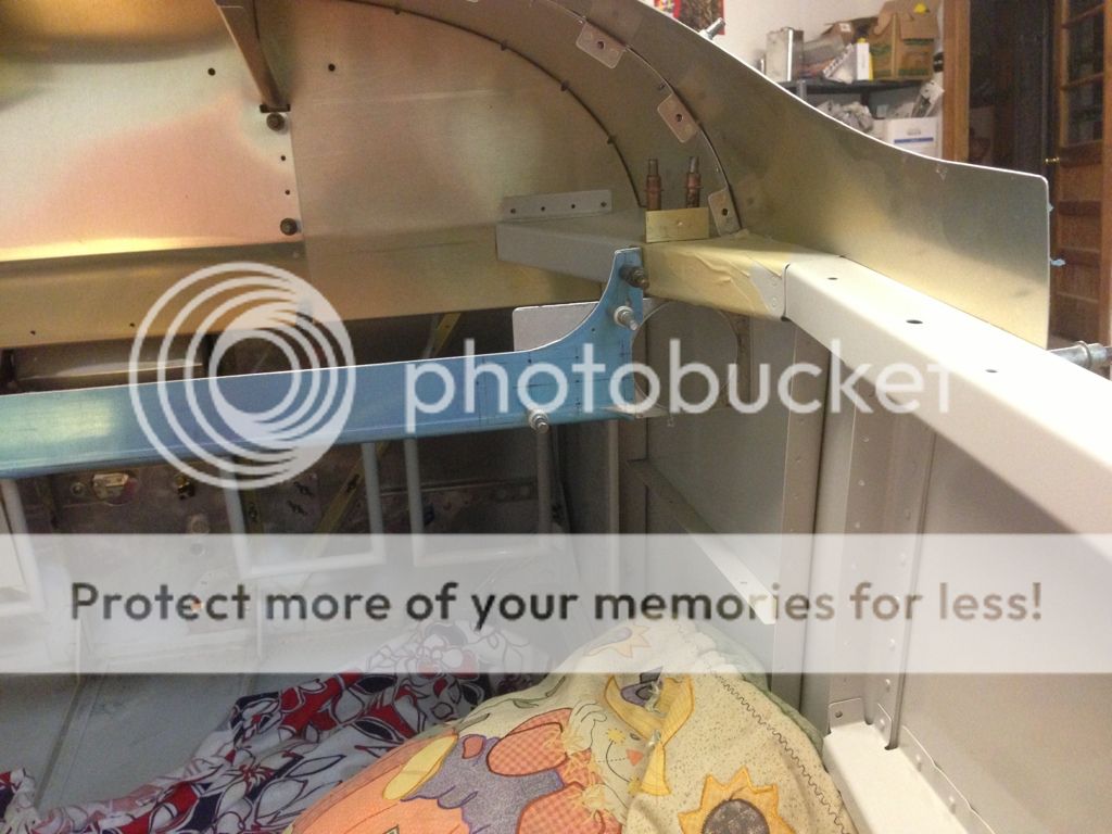
Panel
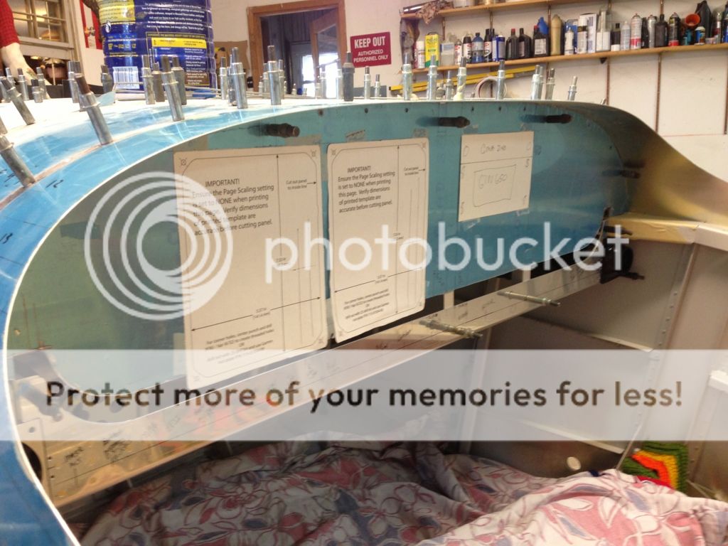
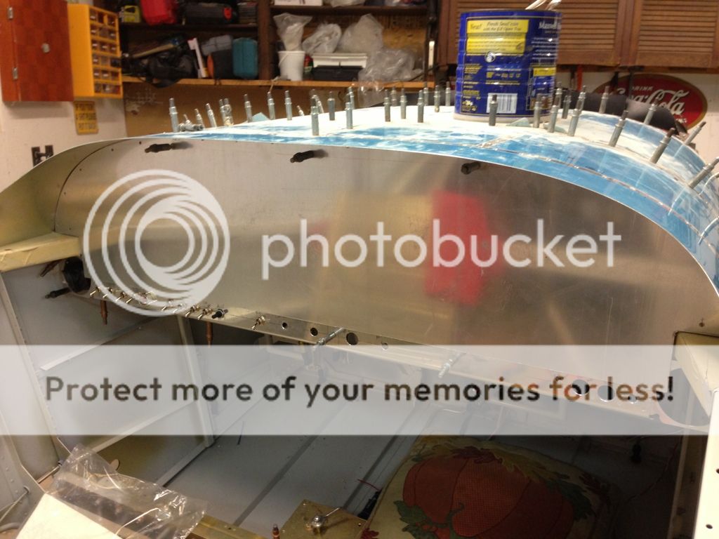
I decided to make the panel 3/4 inch longer to match the bottom of the air vents and give me more of a fudge factor for fitting the avionics and switches. Stock panel theoretically would fit everything. The nutplate between two lines is about 3/8 inch for overlap of panel face. The face itself is another 3/8 taller for the total 3/4 inch.
I'm trying to piece it together without buying to much extra metal, hopefully it won't look pieced together when I'm done.
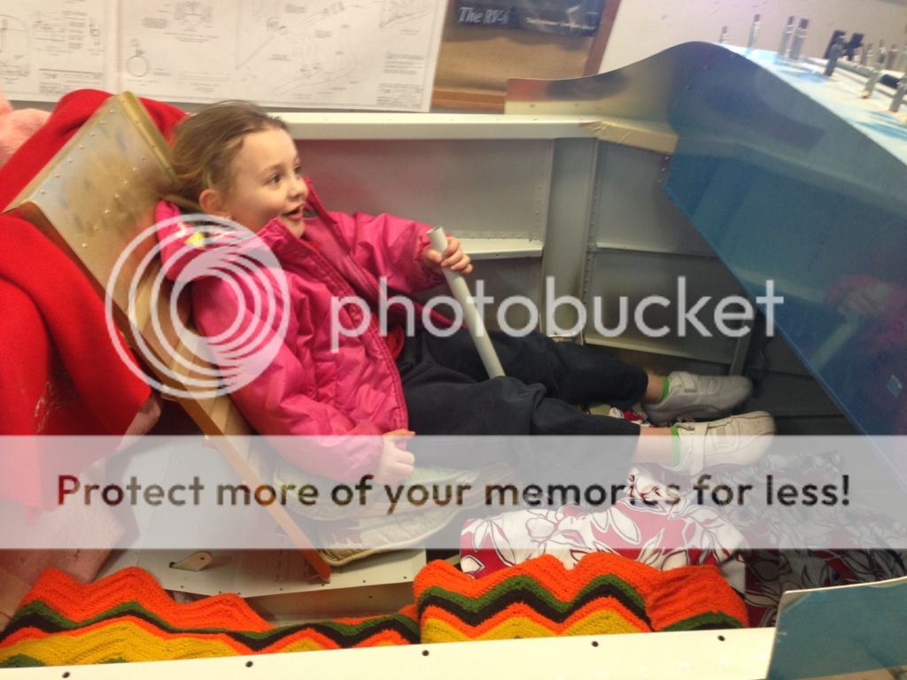
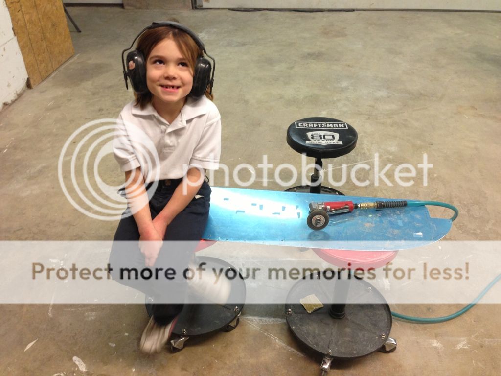
I really need a bandsaw but at this point in the project I'm pretty handy with the die grinder and with my daughter holding the workpiece it came out very straight.
In the panel, next to work on the vent attachments.
I decided to make the panel 3/4 inch longer to match the bottom of the air vents and give me more of a fudge factor for fitting the avionics and switches. Stock panel theoretically would fit everything. The nutplate between two lines is about 3/8 inch for overlap of panel face. The face itself is another 3/8 taller for the total 3/4 inch.
I'm trying to piece it together without buying to much extra metal, hopefully it won't look pieced together when I'm done.
I really need a bandsaw but at this point in the project I'm pretty handy with the die grinder and with my daughter holding the workpiece it came out very straight.
In the panel, next to work on the vent attachments.
Last edited:
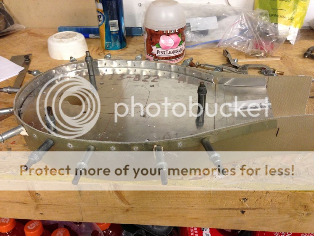
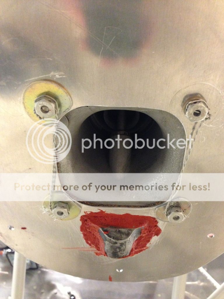
FAB to carb mounting plate, I used a homemade cork gasket between the plate and the carb as well as area washers to hopefully help keep it from cracking.
Still trying to come up with a decent seal between the cowl and the FAB, the plans way seems to be backwards to me but here's a version of it. Seems like I should attach and seal the fabric to the outside of the cowl scoop and have the fabric lay on the inside of FaB.
Still trying to come up with a decent seal between the cowl and the FAB, the plans way seems to be backwards to me but here's a version of it. Seems like I should attach and seal the fabric to the outside of the cowl scoop and have the fabric lay on the inside of FaB.
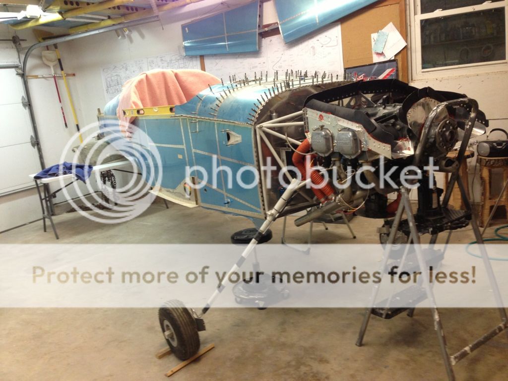
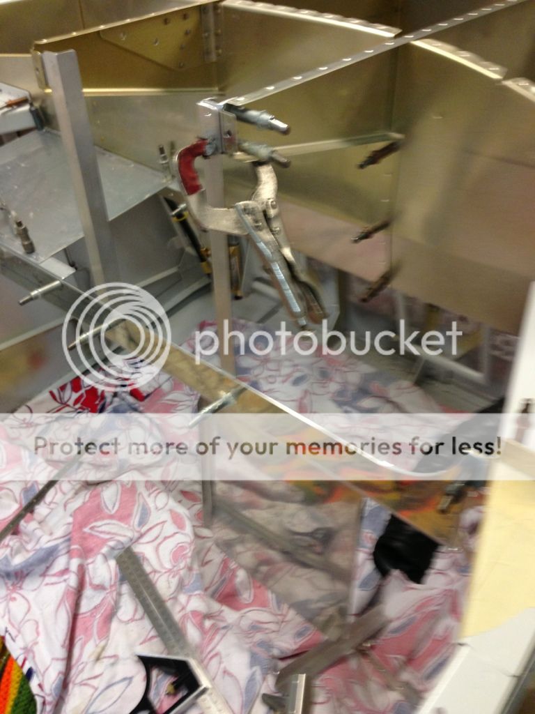
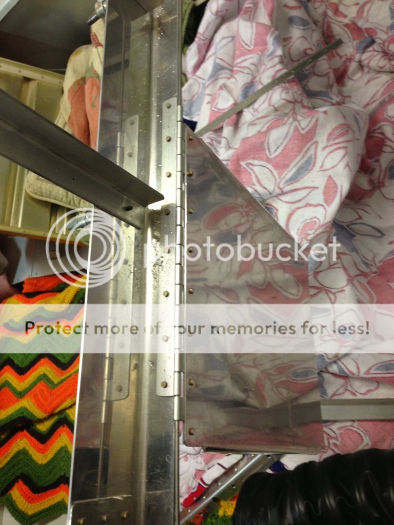
I had to step away from the FAB to cowl seal. Installed the exhaust minus muff and tailpipe supports. One crossover pipe was slightly egg shaped, Larry said it was normal and to just tap it (don't get mad at it) back into round with a rubber mallet, once the pipes expand a couple of times they will find their own fit.
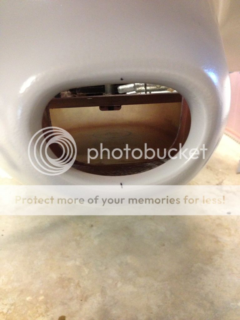
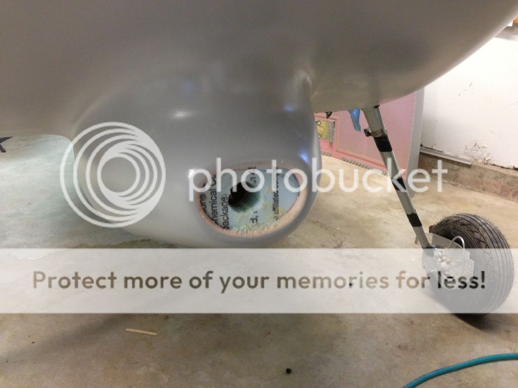
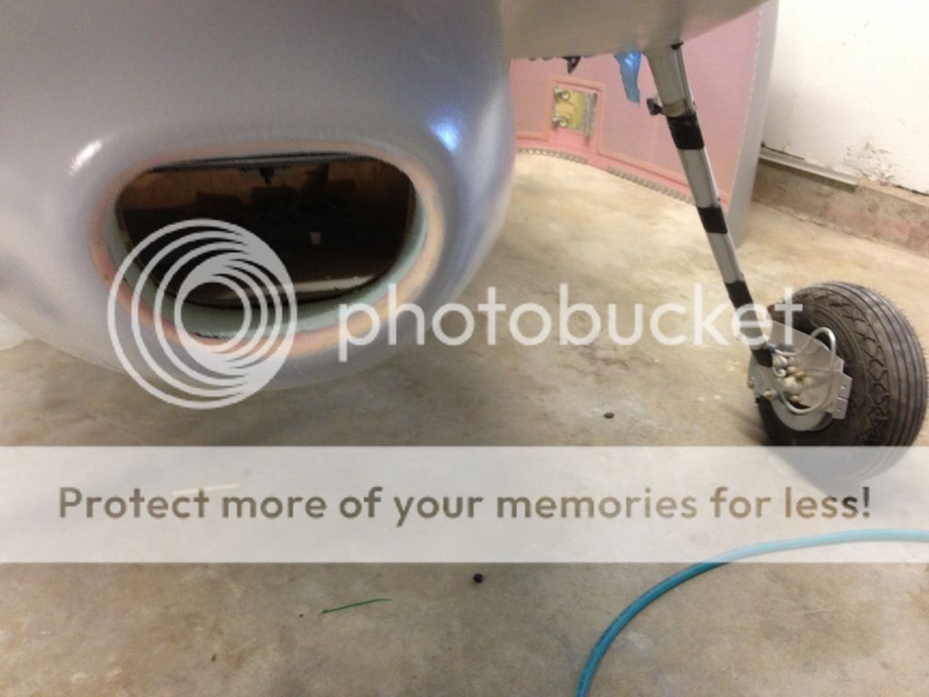
I cutoff and reglassed the front of the FAB to make the inside flush with the outside of the cowl scoop.
I made a clamp and will glue and seal it for final fitting.
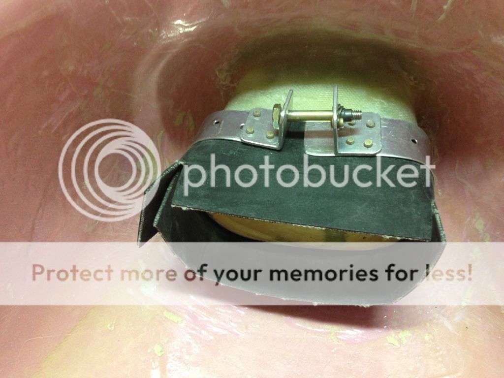
Tuck the fabric inside the cowl scoop and fit cowl and its close, just a tad more trimming to get it to lay flat.

I made a clamp and will glue and seal it for final fitting.
Tuck the fabric inside the cowl scoop and fit cowl and its close, just a tad more trimming to get it to lay flat.
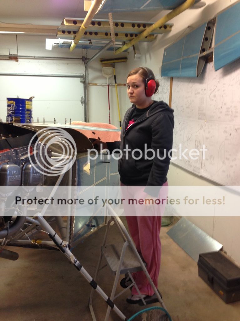
The wife was less than enthused about bucking rivets, but she did a great job!
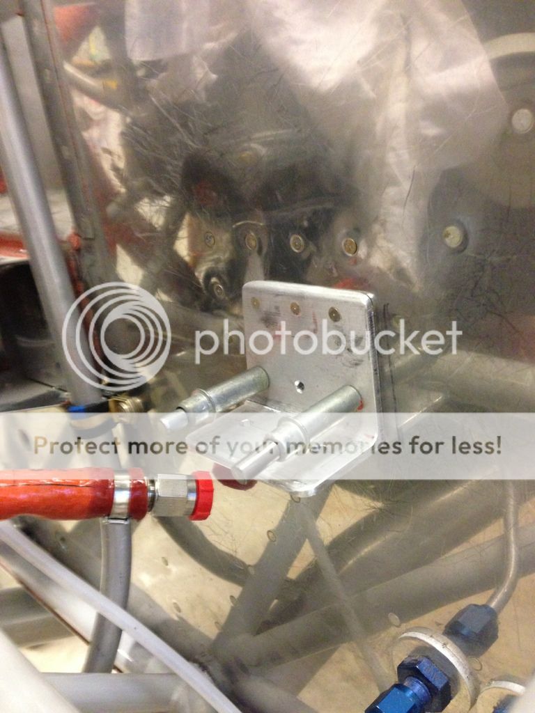
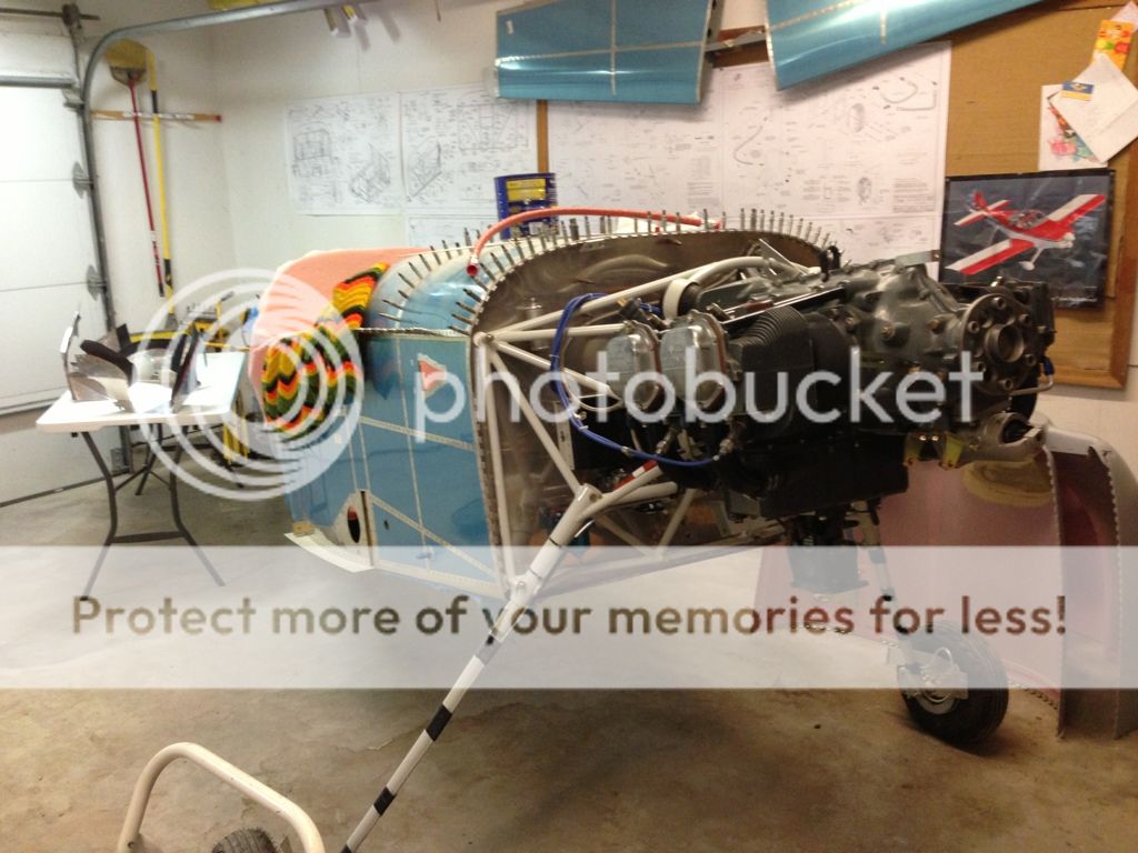
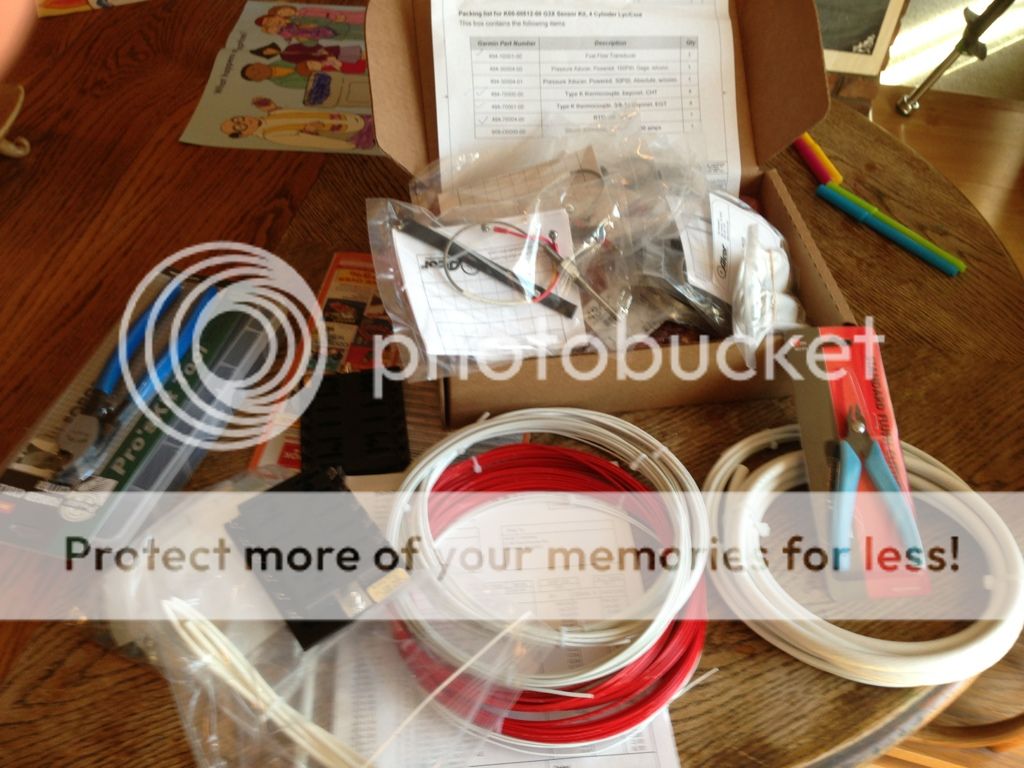
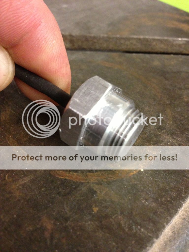
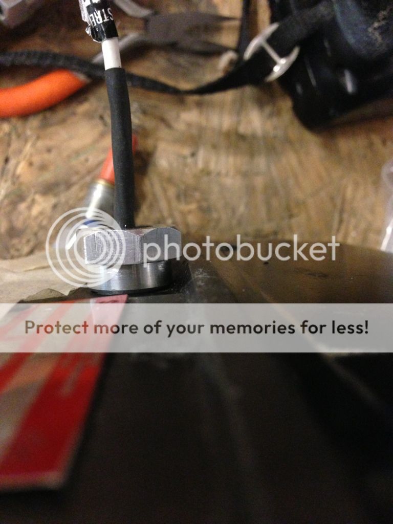
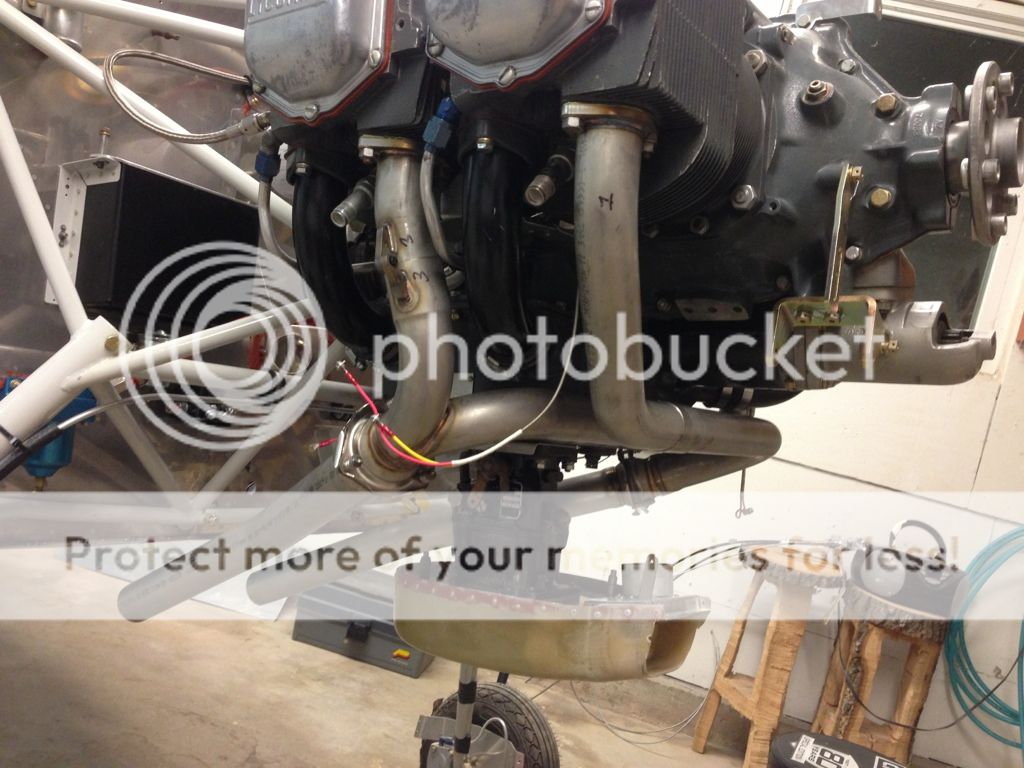
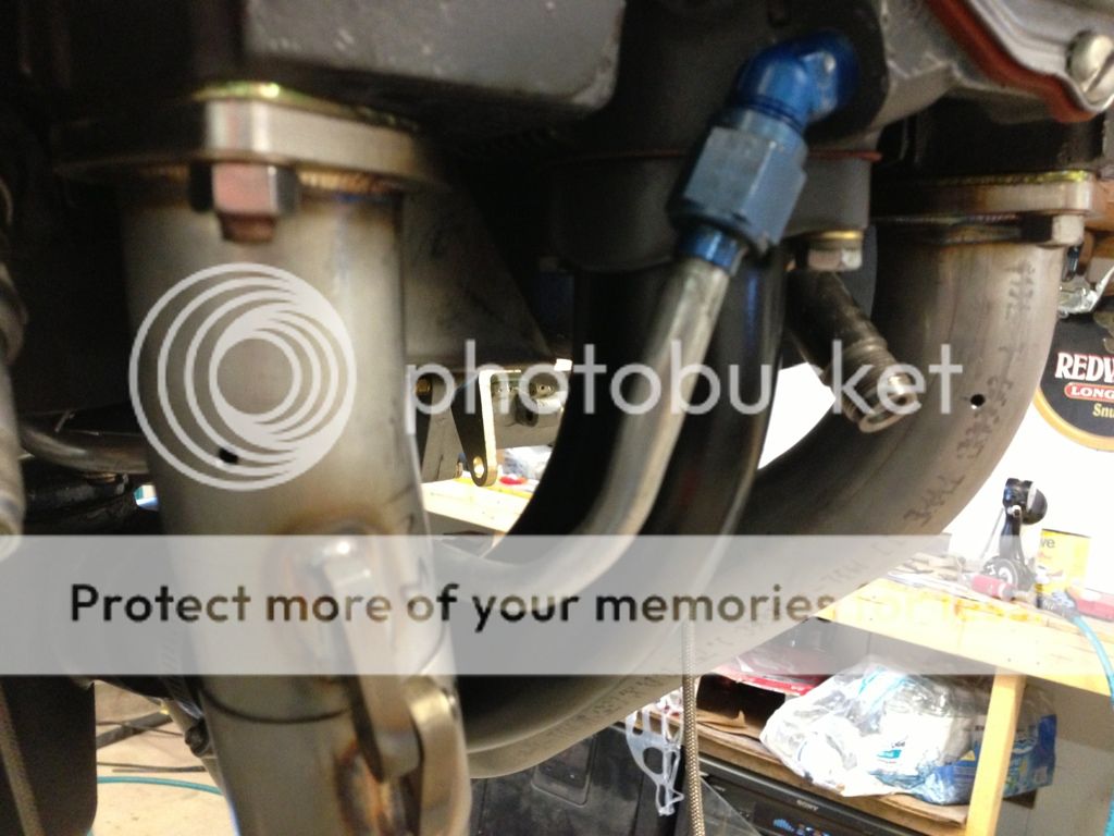
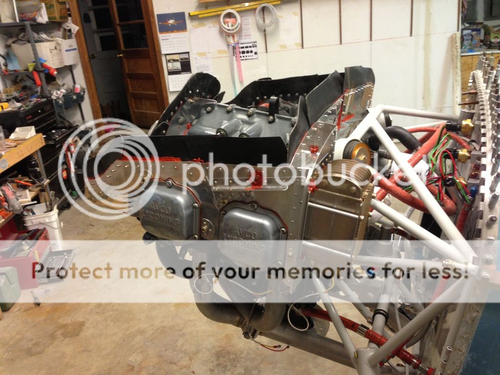
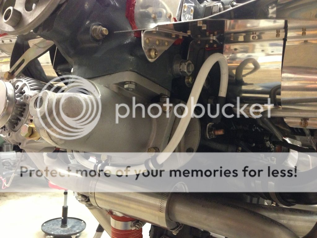
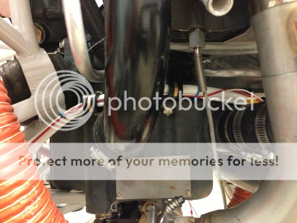
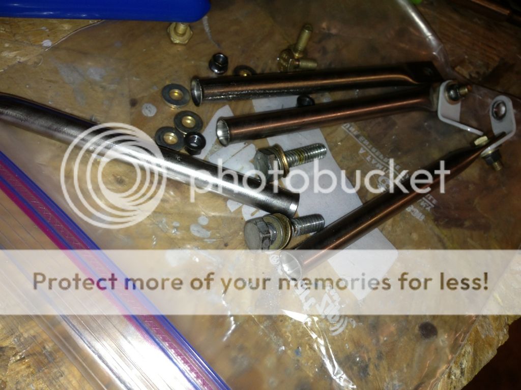
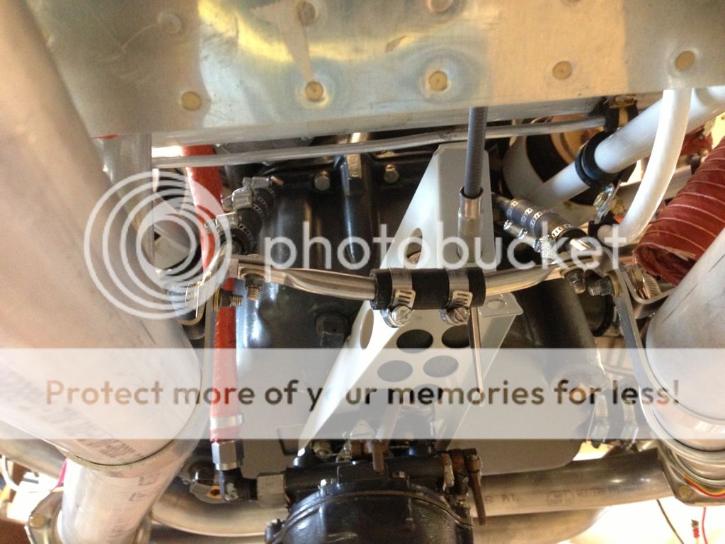
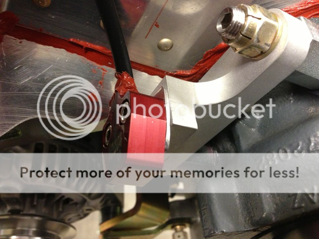
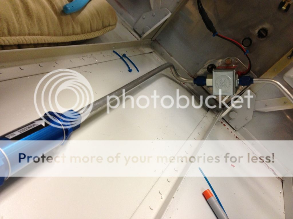
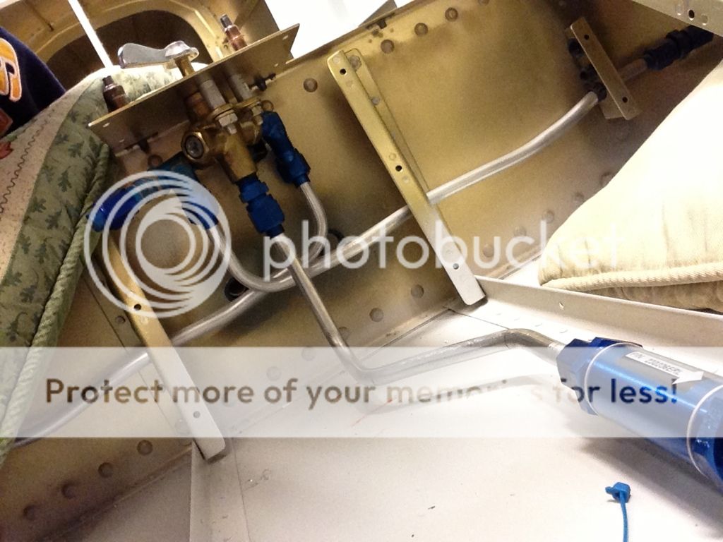
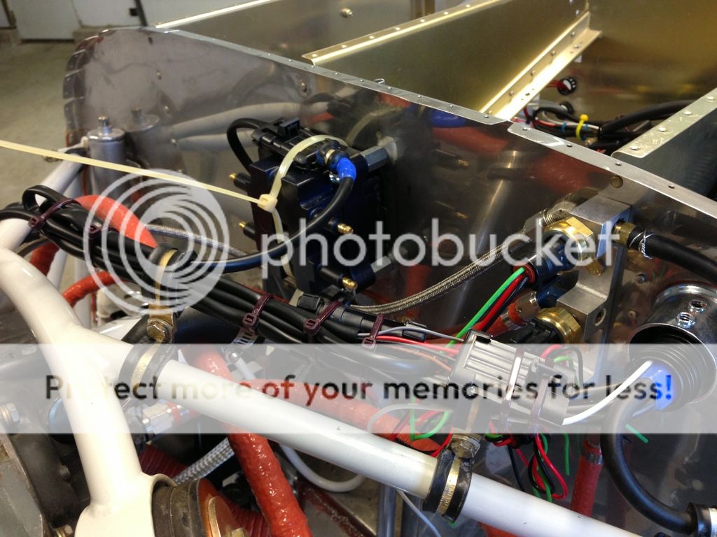
For fitting purposes I used Vans Va-138 fuel hose (gascolator to fuel pump) to go from the fuel pump to the transducer and from the transducer to the carb. TS Flightlines is fabbing up my hoses for me, as well as trimming 4 other hoses and adding a 90. I used Vans KB-090-T at the fuel pump, a 90 into the transducer, a 45 out of the transducer and a 90 on the carb. This routed the fuel line away from the exhaust very well. I didn't see anything in the red cube directions about 90 or 45 fittings, they wanted the wires up and the out line not to point down. The aluminum fittings are for fitting only, the steel ones are in the mail.
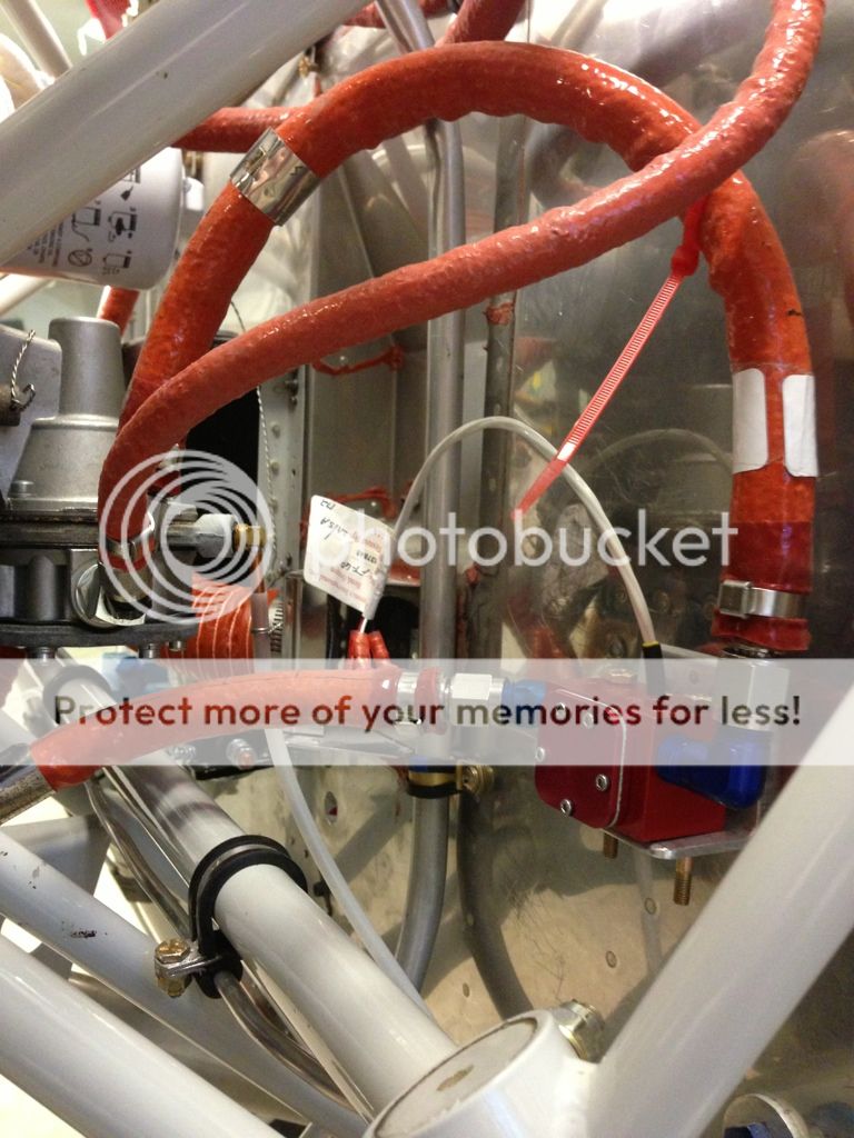
For fitting purposes I used Vans Va-138 fuel hose (gascolator to fuel pump) to go from the fuel pump to the transducer and from the transducer to the carb. TS Flightlines is fabbing up my hoses for me, as well as trimming 4 other hoses and adding a 90. I used Vans KB-090-T at the fuel pump, a 90 into the transducer, a 45 out of the transducer and a 90 on the carb. This routed the fuel line away from the exhaust very well. I didn't see anything in the red cube directions about 90 or 45 fittings, they wanted the wires up and the out line not to point down. The aluminum fittings are for fitting only, the steel ones are in the mail.
Last edited:
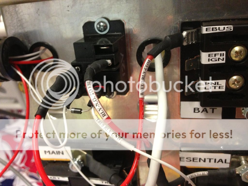
Finally made my mind up and time to move on, aeroelectric diagram Z-13/8. It gives me a lot more options for backup power as i add an autopilot and other flight instruments later. I'm planning on installing the aft firewall stuff now and defer the dynamo and associated stuff till later.
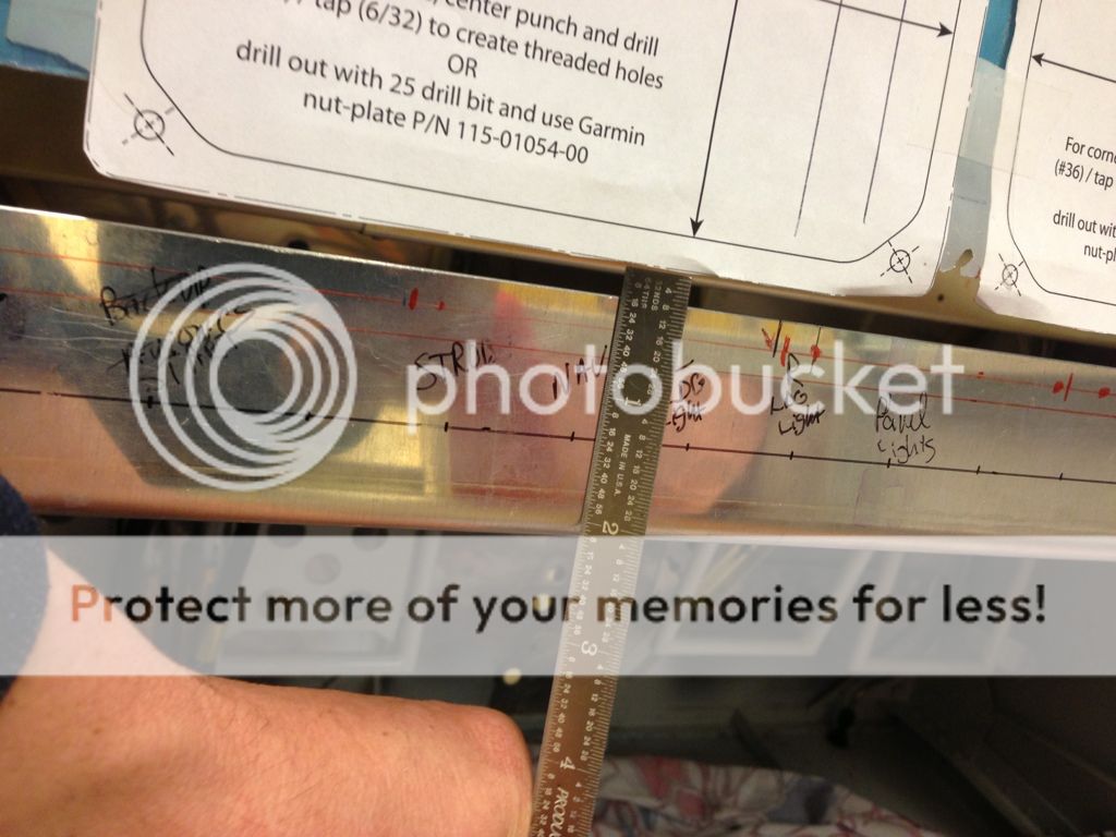
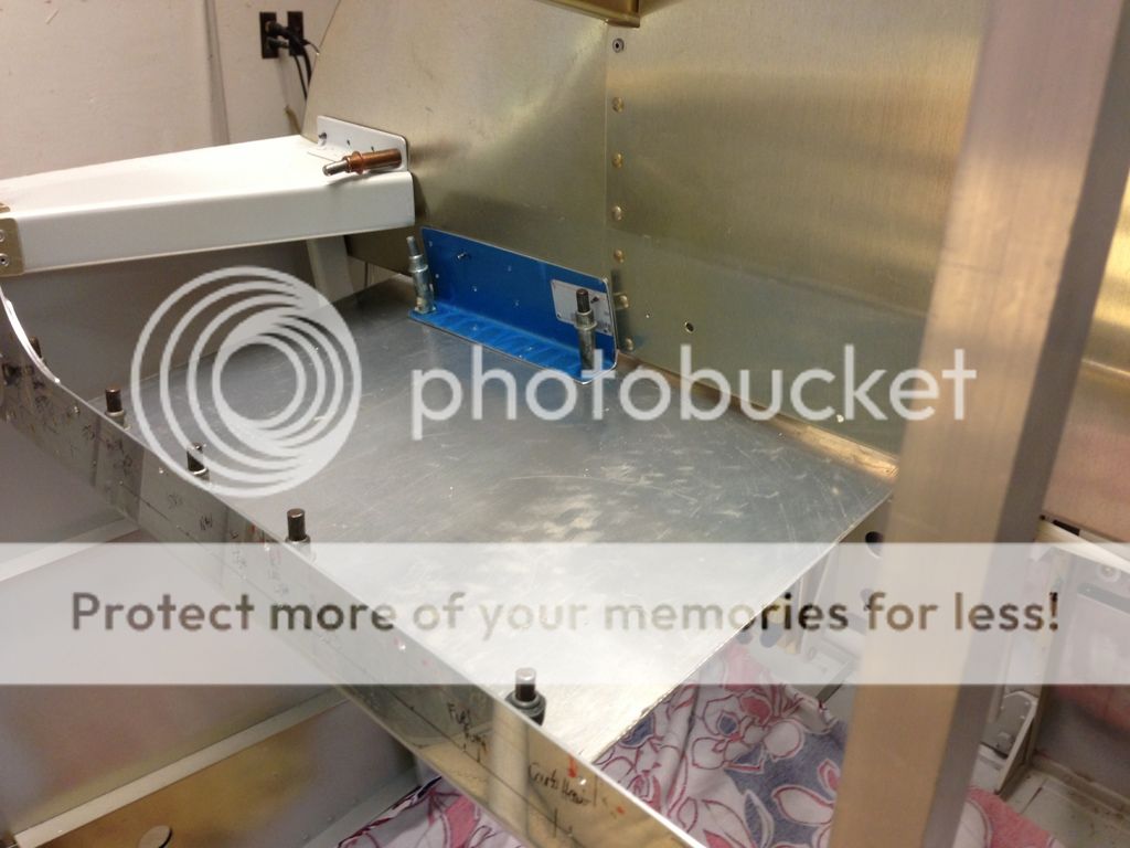
Double checked dimensions for the screws/nutplates on the bottom rail and still have clearance for the switches .
Leveled the plane...the tiltmeter app was pretty handy for the next part.
I laid out the holes for attaching the panel and drilled an angle along the bottom rail. I had to coax the angle to a 100* in order for the top plate to be flat, leveled back and drilled the another angle to the subpanel. The whole assembly is twice as big as I need it so I can mount the GSU 73 in several places and cut down later.
Double checked dimensions for the screws/nutplates on the bottom rail and still have clearance for the switches .
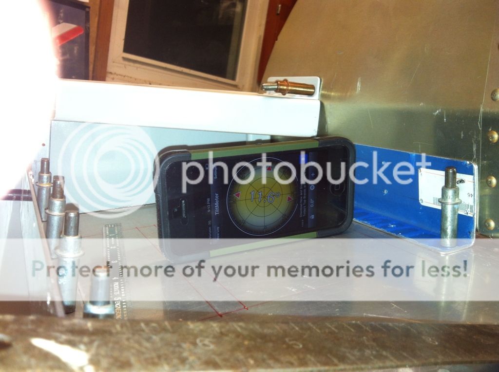
Leveled the plane...the tiltmeter app was pretty handy for the next part.
I laid out the holes for attaching the panel and drilled an angle along the bottom rail. I had to coax the angle to a 100* in order for the top plate to be flat, leveled back and drilled the another angle to the subpanel. The whole assembly is twice as big as I need it so I can mount the GSU 73 in several places and cut down later.
Last edited:
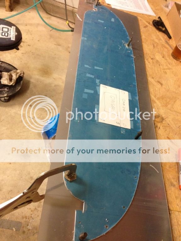
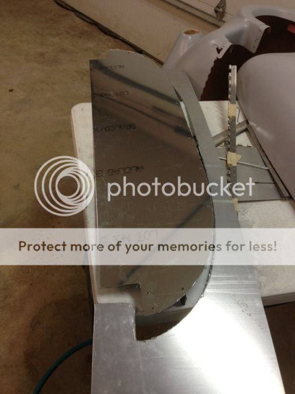
My usual bending brake (bench top and clamps and various plates) wasnt giving acceptable results with the small bend on .063. My local heating and air (thank you Adamson Bros) has an 8 foot brake they let me use. I can't wait to get equipment like that!
Drilled to the lower panel
Drilled to the subpanel.
The tiltmeter app is pretty handy, but probably a little too accurate. I keep trying to readjust to the 10th degree.
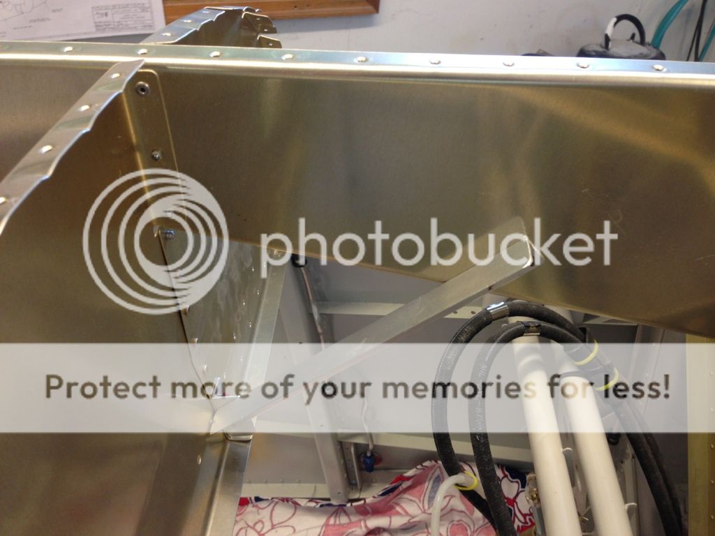
I don't want to add support angles or cut the floor plate down until I actually have the GSU 73 in hand.
Drilled to the lower panel
Drilled to the subpanel.
The tiltmeter app is pretty handy, but probably a little too accurate. I keep trying to readjust to the 10th degree.
I don't want to add support angles or cut the floor plate down until I actually have the GSU 73 in hand.
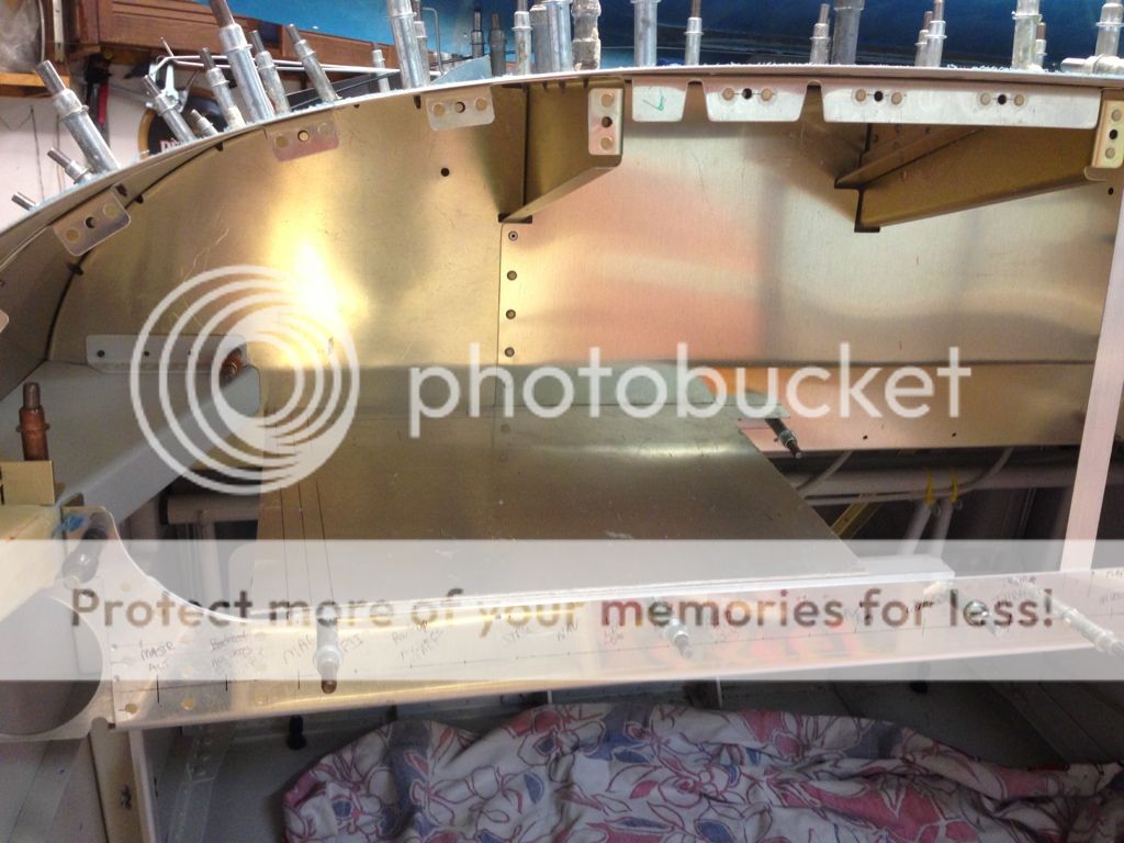
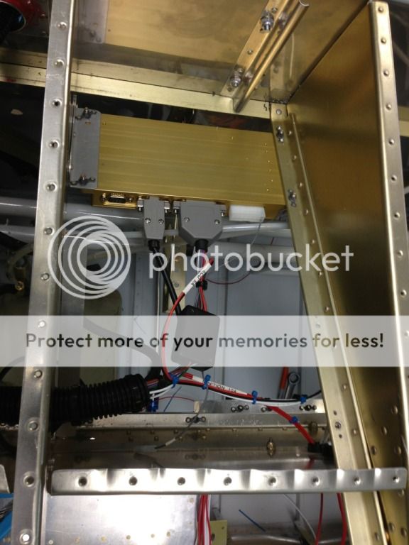
Subpanel cutout and reinforced. Wish I had the radios and didn't have to guess. (looks tweaked but it's square)
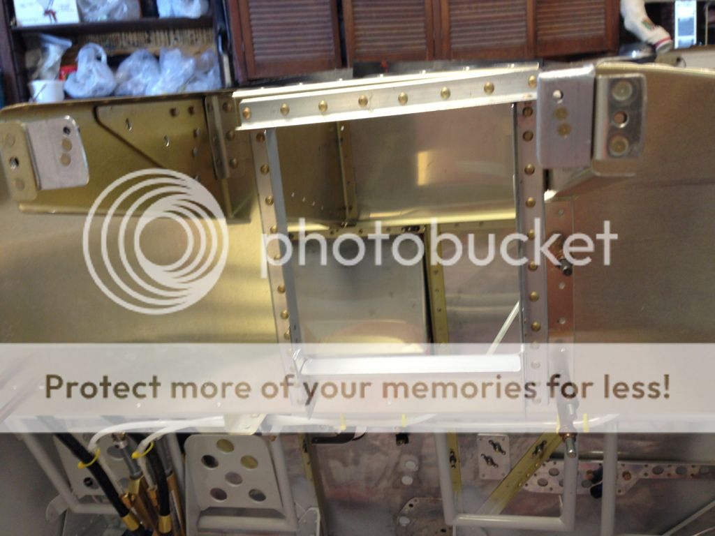
I made a couple of reinforcement angles to stiffen the bottom of the subpanel and GSU 73 floor.
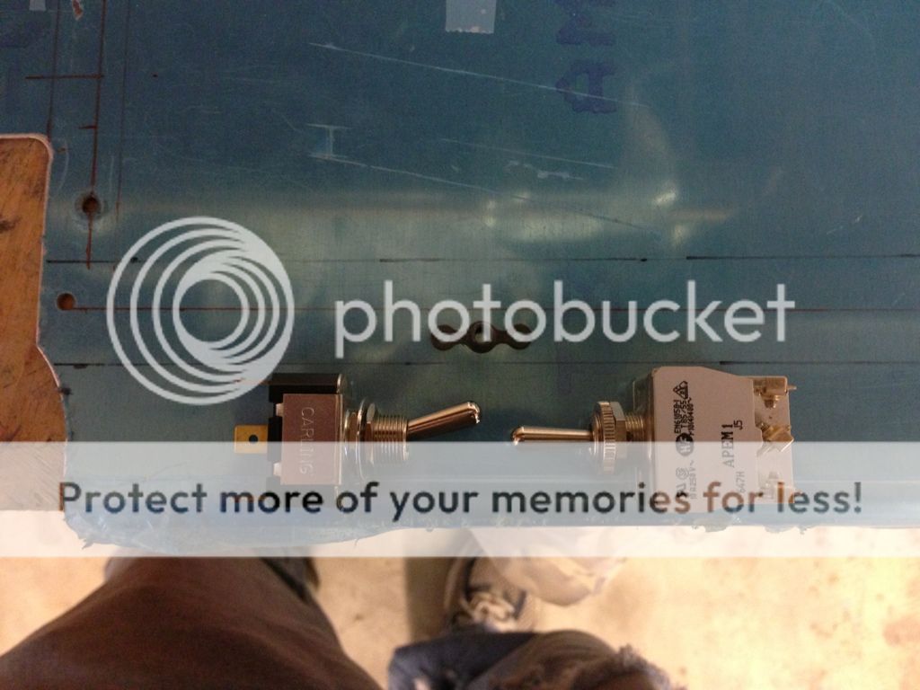
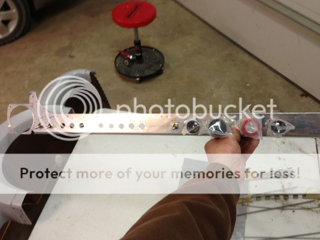
Switches drilled and temporarily installed cables and a couple of switches to check the fit.
I made a couple of reinforcement angles to stiffen the bottom of the subpanel and GSU 73 floor.
Switches drilled and temporarily installed cables and a couple of switches to check the fit.
Last edited:
tkatc
Well Known Member
Not exactly sure what your plan is with the floor pan but I have had to work UNDER the panel of my -7A and would suggest cutting a large access hole in the bottom of that pan. That way you can remove the avionics from the front of the panel and then while UNDER the panel you can reach up to access whatever....wires, pitot tube, etc.
Perhaps you already had this plan though...
Perhaps you already had this plan though...
Thanks for the advice, I'm actually hoping to not work under the panel. I plan on having the G3X screens wired a little long so I can remove them from the front, pull them out and unhook the connectors. The face of the panel will also be removable on both sides of the radio stack. The radio stack will stay in place as well as the lower panel with all of the switches and push pull cables.
I made the floor plate huge to give me several options on mounting the GSU 73, Once I get the actual Garmin pieces in a couple of months I plan on trimming it to fit the final location. It's only like 5 inches square but with the connectors from the screens sticking back several inches it will be kinda tight!
I made the floor plate huge to give me several options on mounting the GSU 73, Once I get the actual Garmin pieces in a couple of months I plan on trimming it to fit the final location. It's only like 5 inches square but with the connectors from the screens sticking back several inches it will be kinda tight!
Last edited:

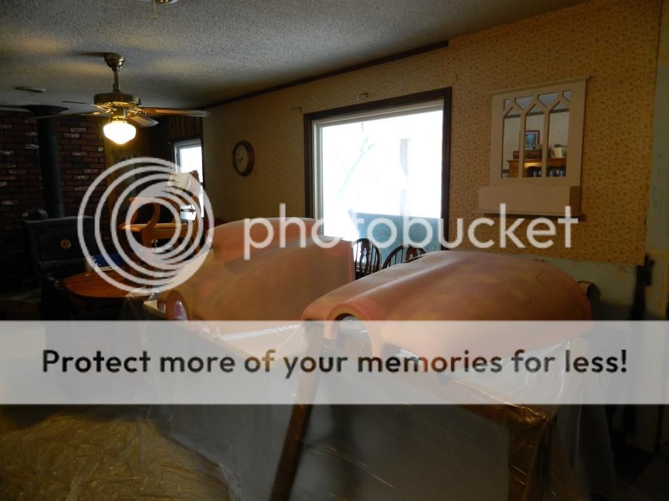
Older cowling pics
Had to use the "inside" garage to get the epoxy to flow for pinholes.
Initial layout of my hinge covers.
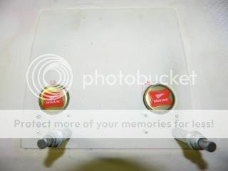
After I reinforced my oil door with a couple of extra layers of fiberglass, my flush latch camlocks were no longer flush. It took me a couple of weeks but I found these laying around to fill the void.
Had to use the "inside" garage to get the epoxy to flow for pinholes.
Initial layout of my hinge covers.
After I reinforced my oil door with a couple of extra layers of fiberglass, my flush latch camlocks were no longer flush. It took me a couple of weeks but I found these laying around to fill the void.
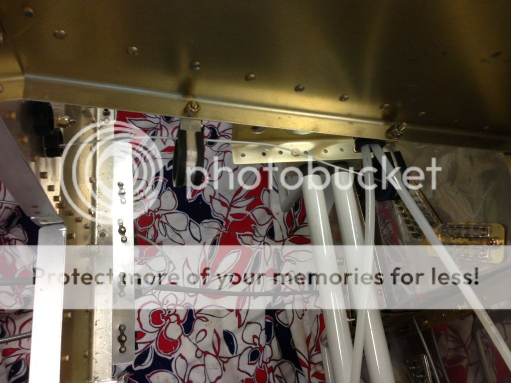
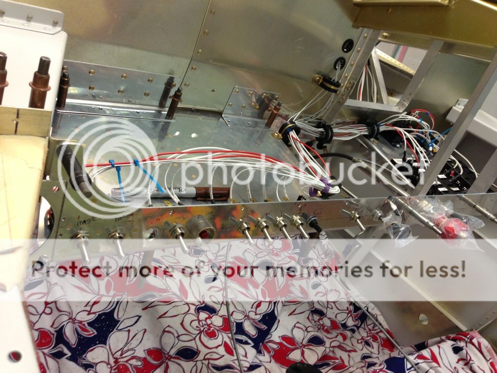
Making more decisions on various wiring runs, the panel will remain hinged for now.
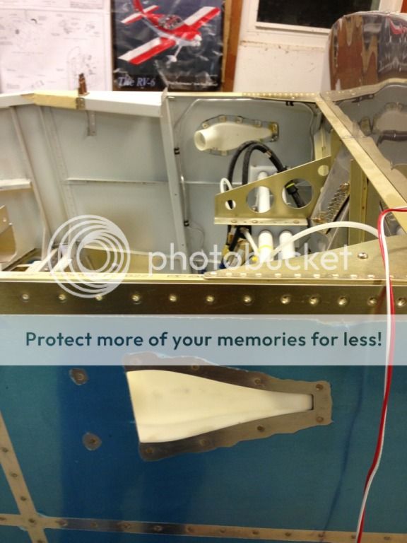
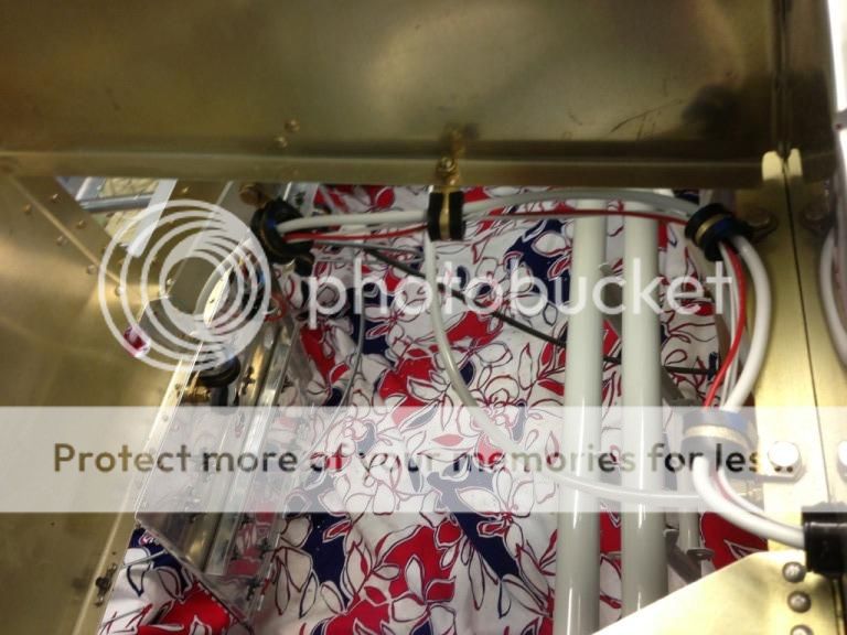
Back side: I'm surprised how small of a service loop it actually takes to rotate the panel with the wires run this way.
Front of the panel: there is less than an inch of motion between the adel on the fuse panel and the adel on the sub panel, we'll see if the panel remains moveable after the wire bundles grow.
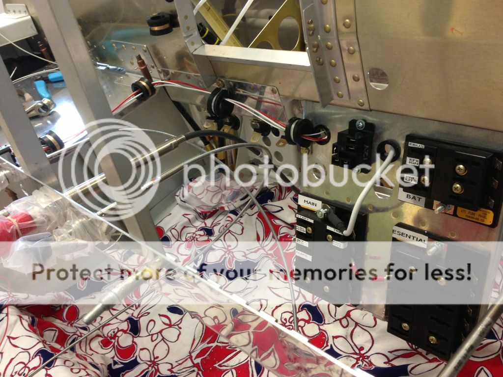
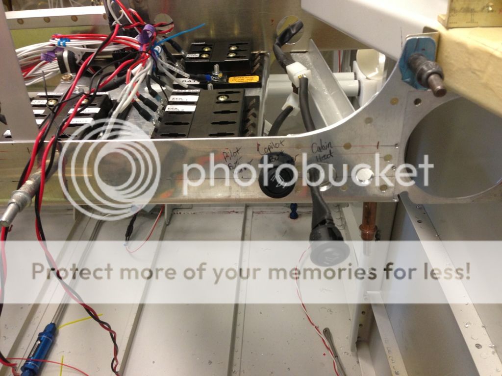
I think I'm going to run the grounds through the center of the sub panel and down the bottom side of the forward rib to the forest of tabs on the firewall recess. Disregard the forest of tab orientation and location, it just kinda happened that way.
Back side: I'm surprised how small of a service loop it actually takes to rotate the panel with the wires run this way.
Front of the panel: there is less than an inch of motion between the adel on the fuse panel and the adel on the sub panel, we'll see if the panel remains moveable after the wire bundles grow.
I think I'm going to run the grounds through the center of the sub panel and down the bottom side of the forward rib to the forest of tabs on the firewall recess. Disregard the forest of tab orientation and location, it just kinda happened that way.
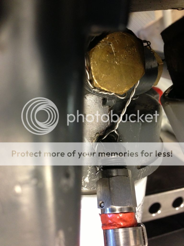
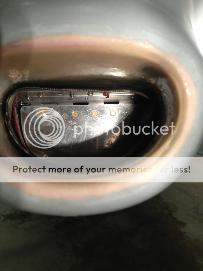
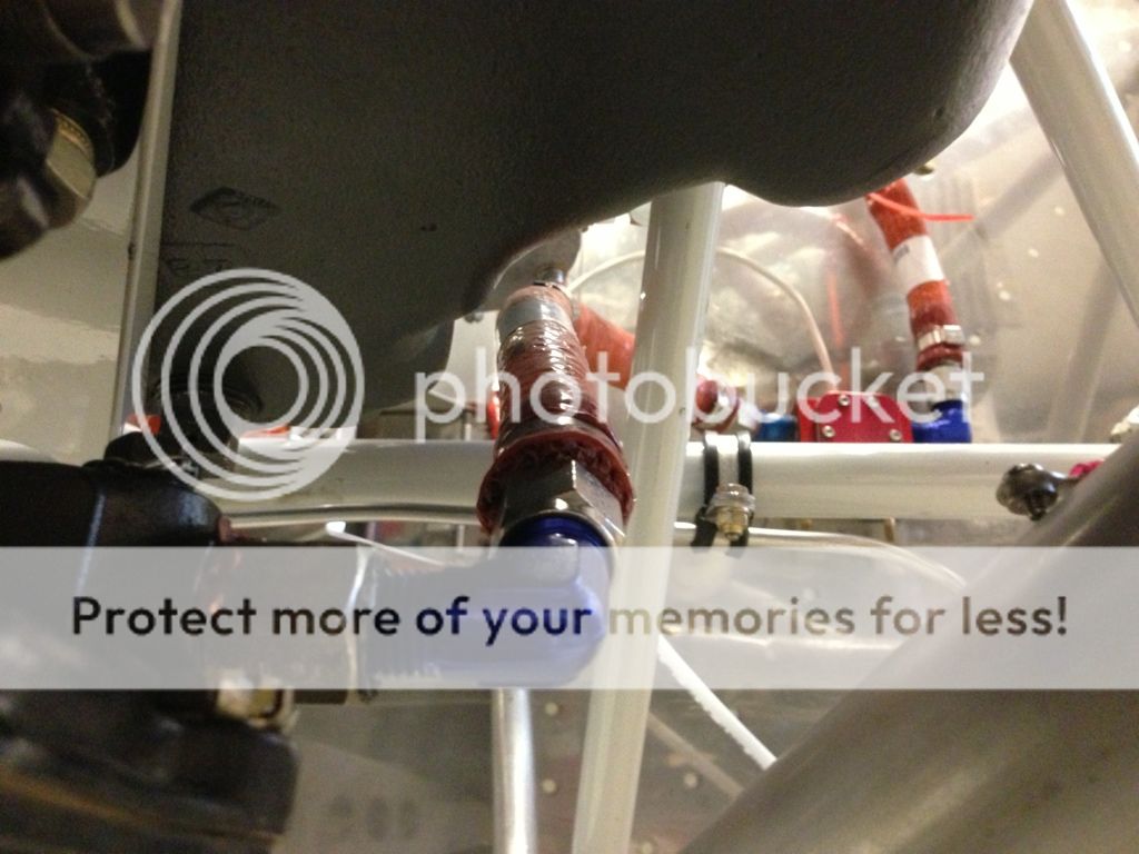
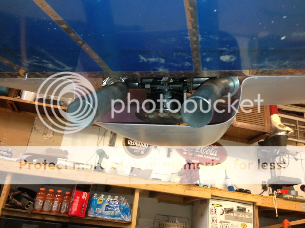
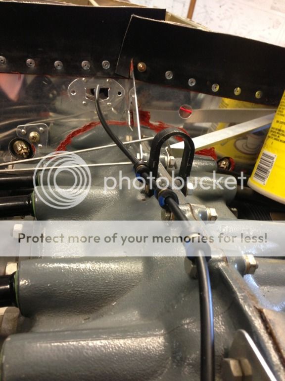
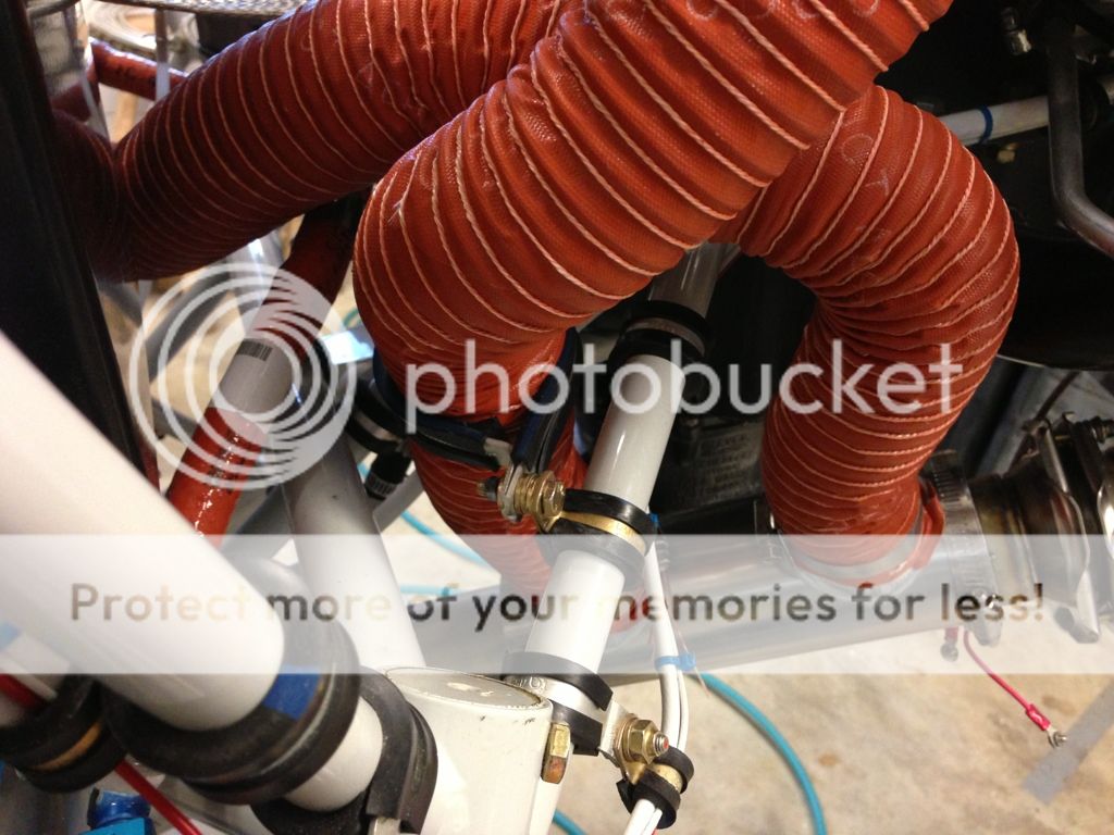
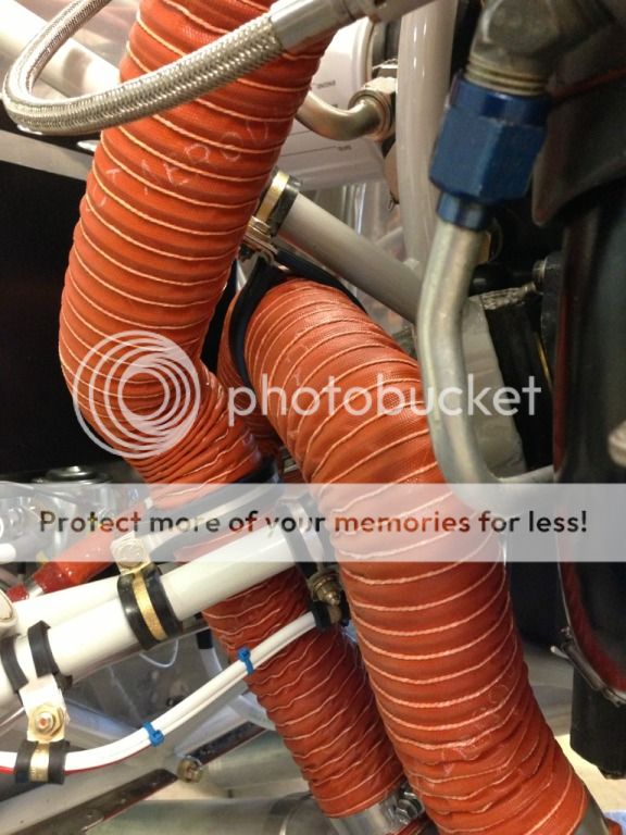
I positioned the exhaust tailpipes, I left the balljoint loose so I could twist them into position. I got the required 25 degrees down from the belly, but the best clearance from the cowl to heat muff is only 1/2-5/8 inch. I will look into some heat sheilds. The tailpipes do slightly angle towards each other.
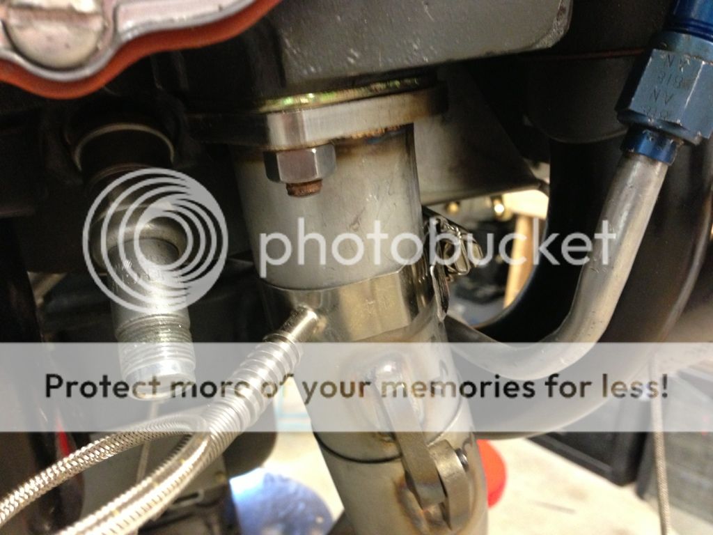
I finally fit the tailpipe hangers on the right side, but as others has posted the rubber slips on the tube (I cleaned both ss and rubber inside and out with acetone) with 3-5 lbs of downforce. I roughened up the tubes with a file, added a slight flare with my new flaring tool and doubled the hose clamps.
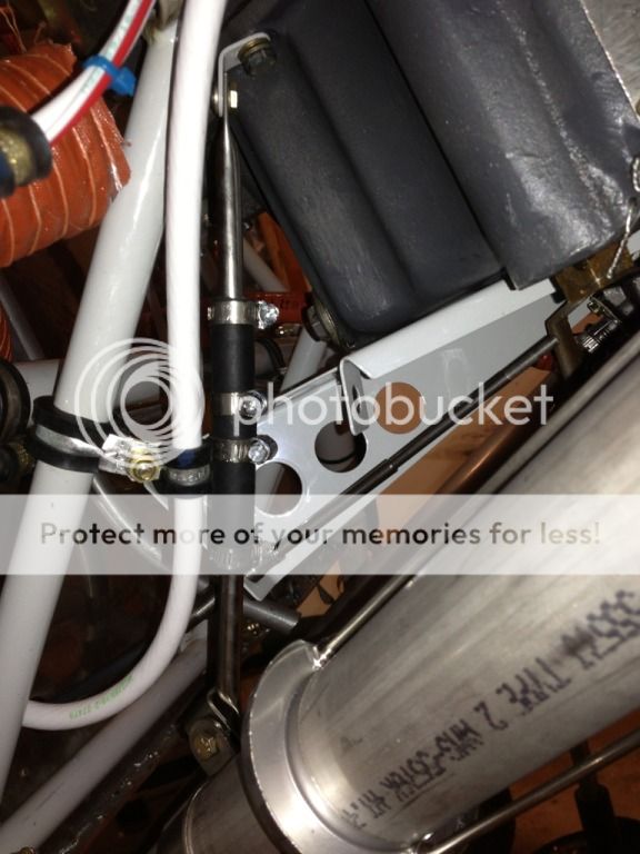
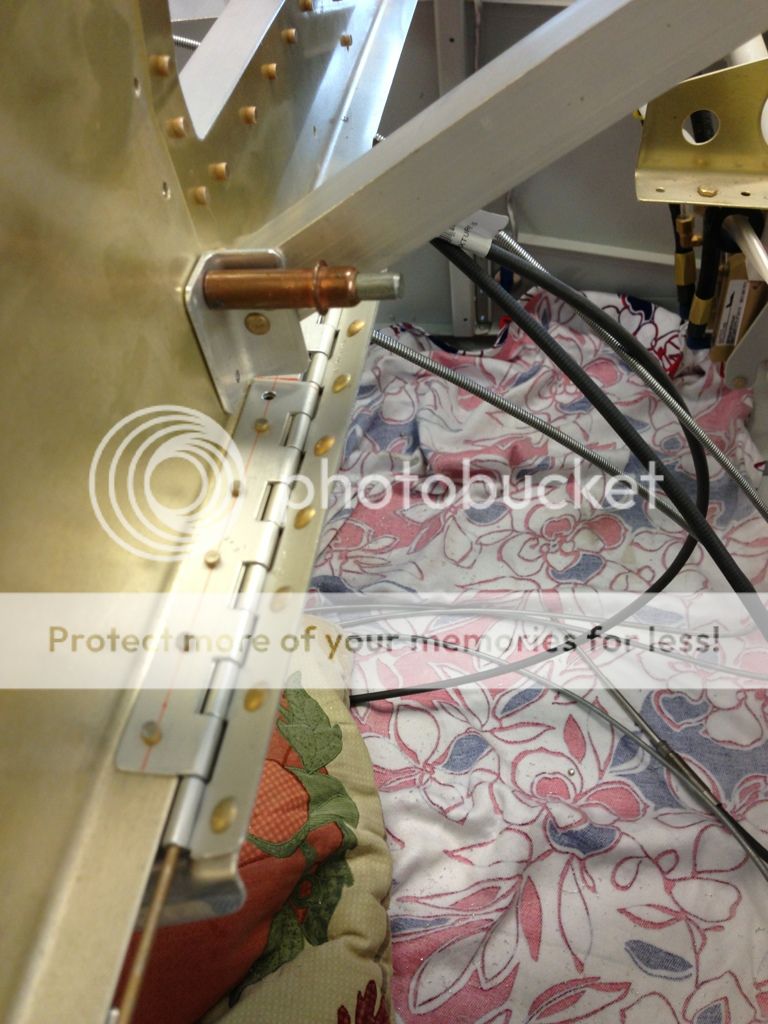
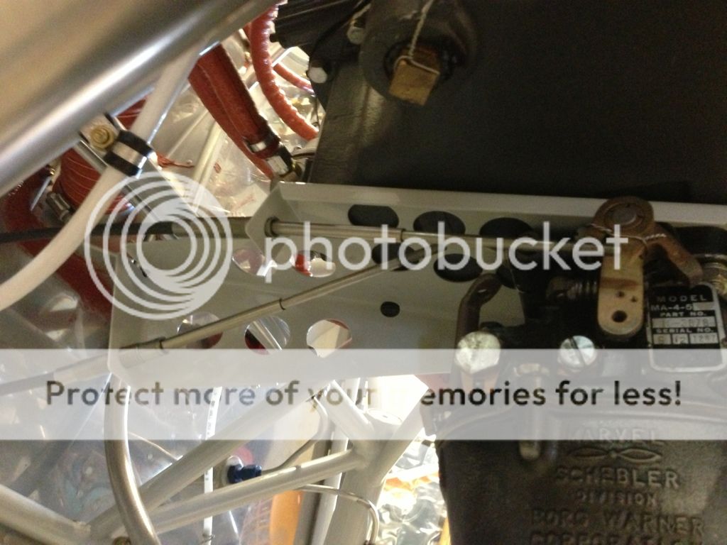
I had to fit the hanger between the throttle cable and starter cable, the left side is just inside my fuel line to the carb. I really want to come up with something better, but it can wait till after I'm flying.
I finally fit the tailpipe hangers on the right side, but as others has posted the rubber slips on the tube (I cleaned both ss and rubber inside and out with acetone) with 3-5 lbs of downforce. I roughened up the tubes with a file, added a slight flare with my new flaring tool and doubled the hose clamps.
I had to fit the hanger between the throttle cable and starter cable, the left side is just inside my fuel line to the carb. I really want to come up with something better, but it can wait till after I'm flying.
Last edited:
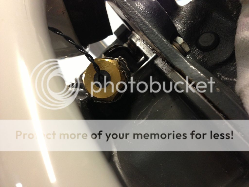
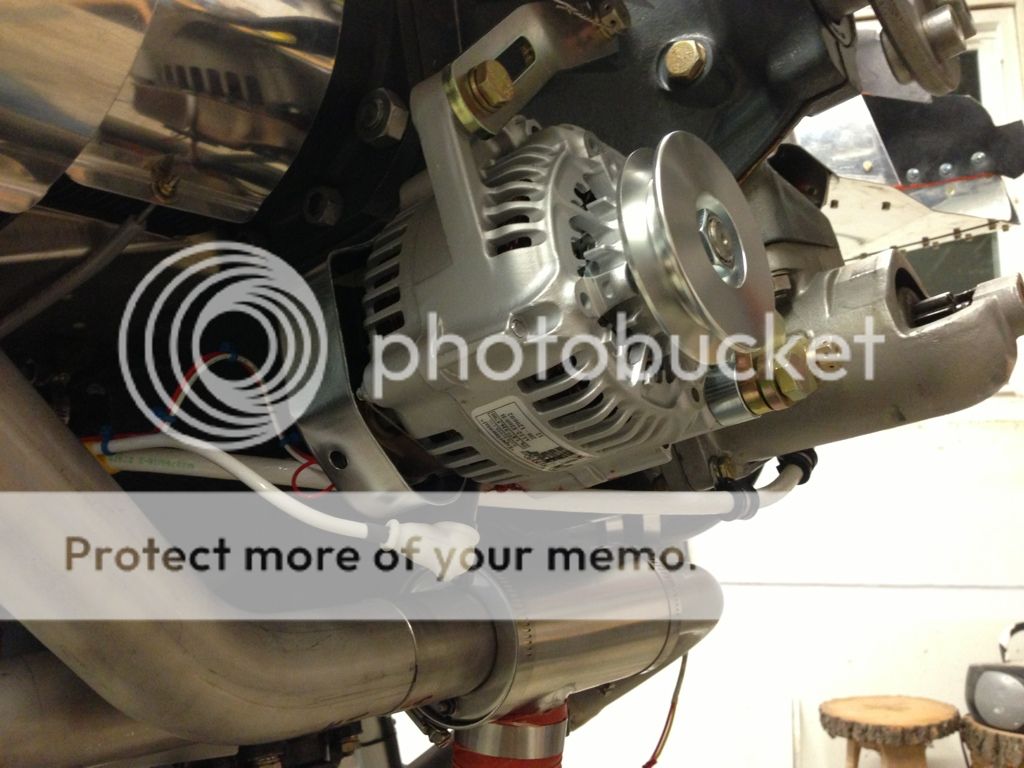
My EFII ignition came today! I mailed my flywheel to Protek about a month and a half ago, they put in the 3 magnets for the flywheel pickup.
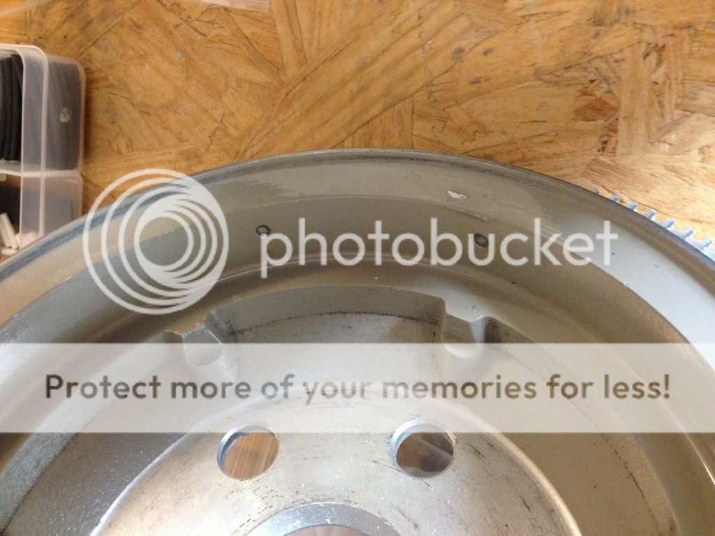
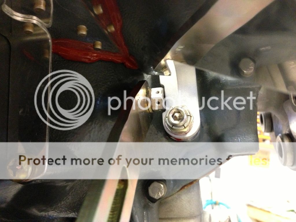
Here's a shot of the flywheel pickup.
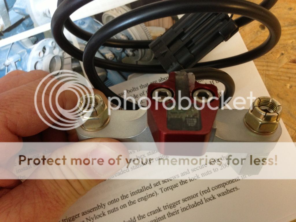
Installed via the existing case bolts, no drilling or positioning required.
The alternator braket bolt must be installed first.
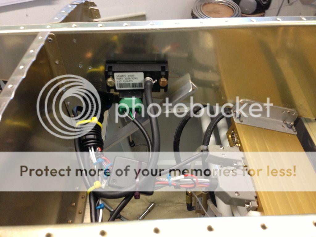
I mounted the ECU on to the angle brace on the center rib (slider) and added an angle to the left rib.
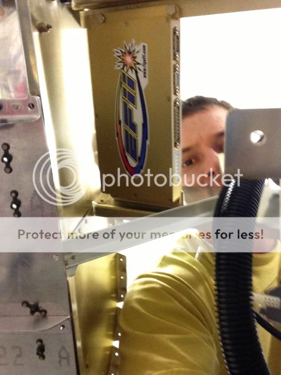
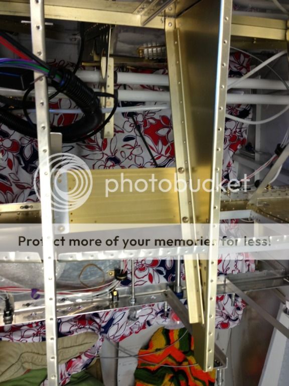
Downside is the wiring harness and connectors are pretty large.
Here's a shot of the flywheel pickup.
Installed via the existing case bolts, no drilling or positioning required.
The alternator braket bolt must be installed first.
I mounted the ECU on to the angle brace on the center rib (slider) and added an angle to the left rib.
Downside is the wiring harness and connectors are pretty large.
Last edited:
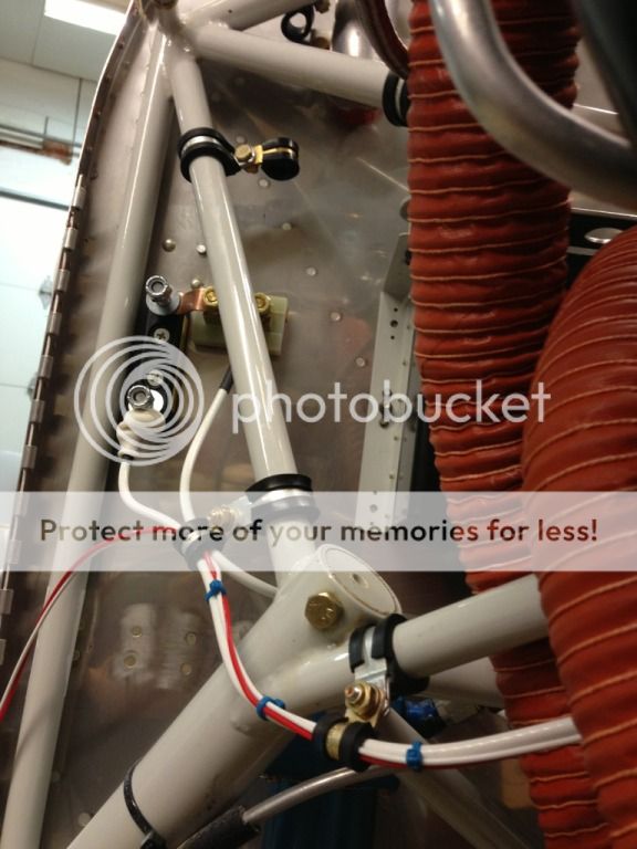
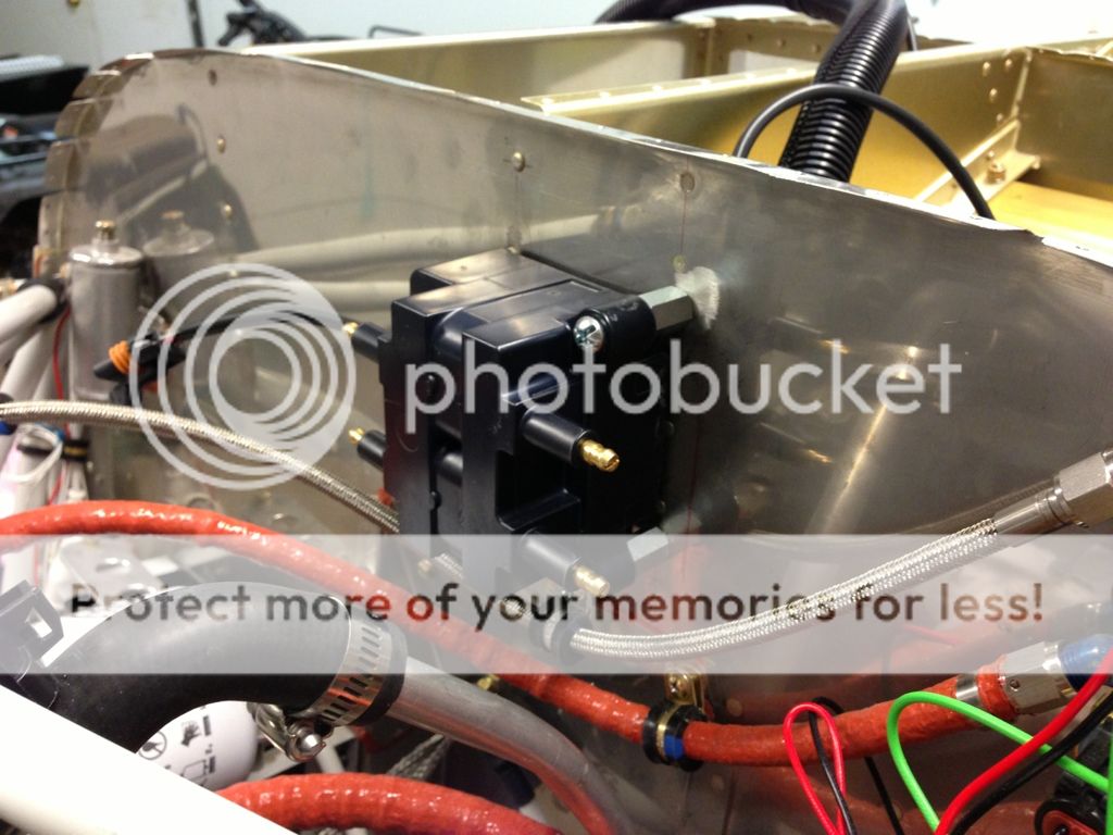
Pic of the coil mounted on the firewall. It came with a nice mag blockoff plate and coil mount, but I've got the single mag accessory case. I was going to mount it on the lower accessory pad but the firewall was easier.
Stiffener on the back of the firewall.
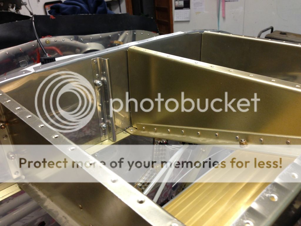
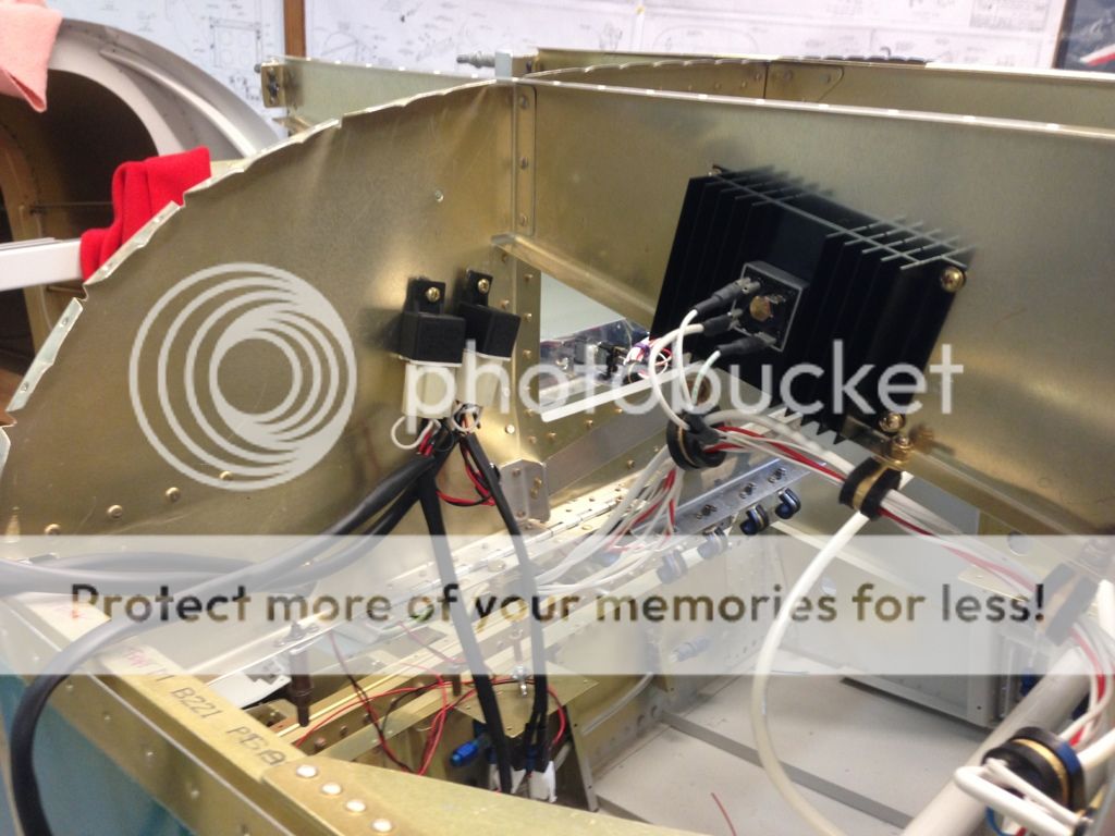
Heat sink for the essential bus diode.
Stiffener on the back of the firewall.
Heat sink for the essential bus diode.
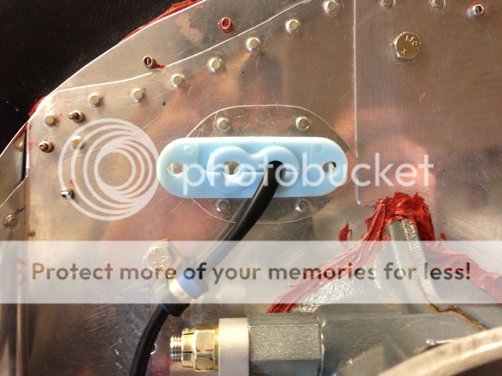
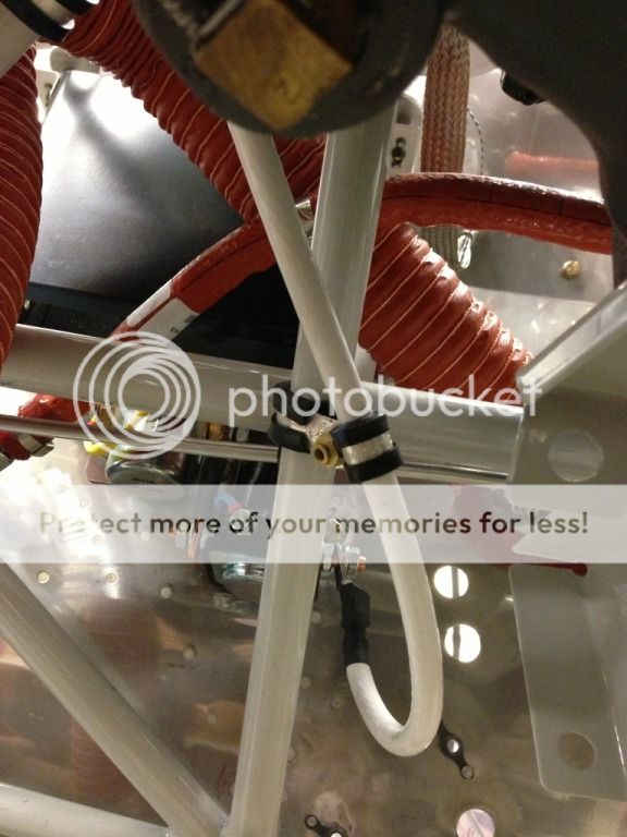
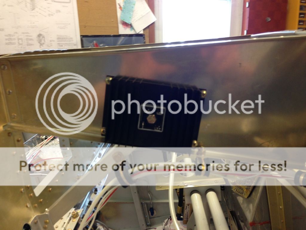
Strobe mount, I'm running all of the strobe wires on the right side leaving the left side free for the magnometer wire. I trimmed the back of the mount for the rudder cables, added some safety wired tube just in case and added J channel stiffeners and nutplates for Adels at the bottom.
I got my butt Warmers from flyboys today.
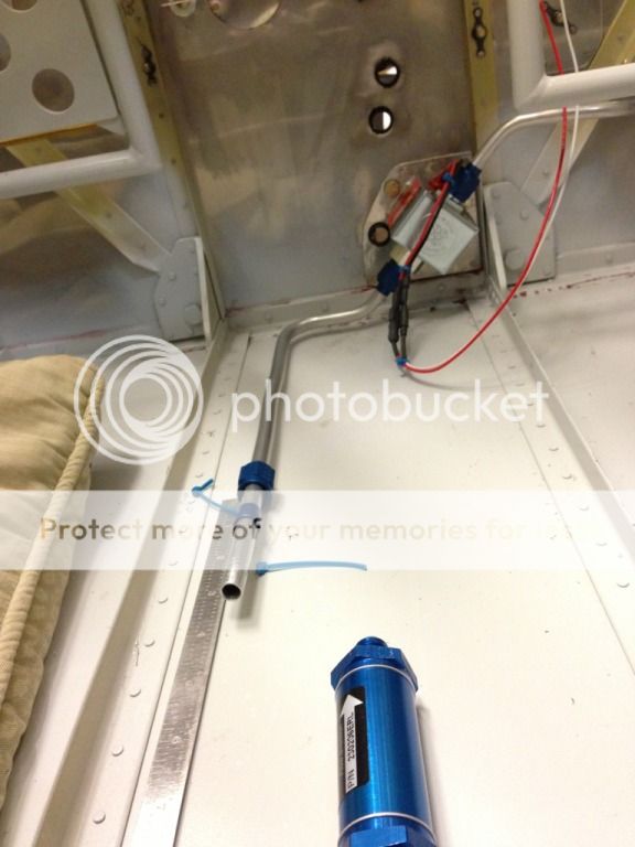
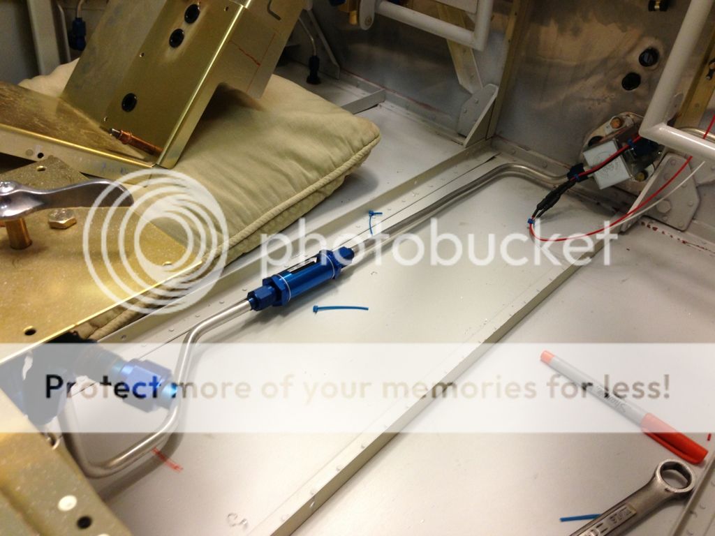
I made the first fuel line on the first try.
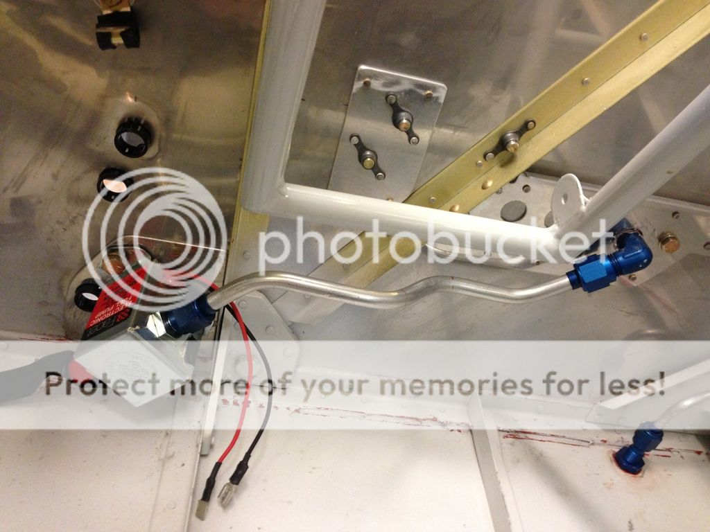
My first fuel line from selector to pump.
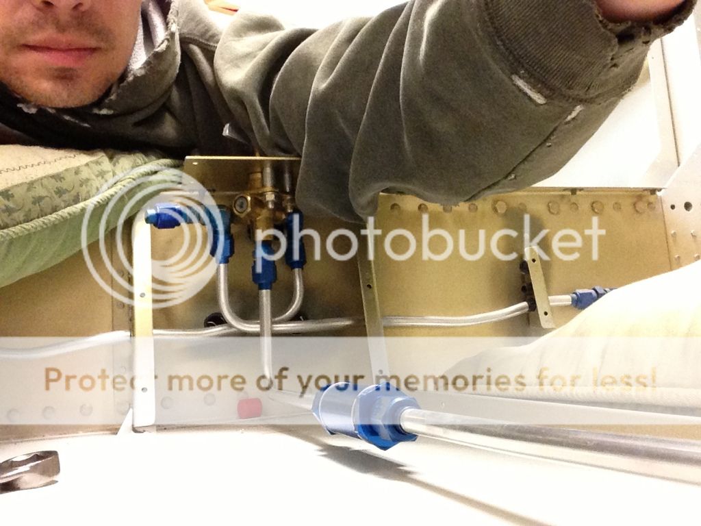
I made the original bend 90 from the pump and then 45 to the floor and it was too high. The second line I made lays nicer and is 45 from the pump then 90 to the floor but I have to remake the other line now.
I got my butt Warmers from flyboys today.
I made the first fuel line on the first try.
My first fuel line from selector to pump.
I made the original bend 90 from the pump and then 45 to the floor and it was too high. The second line I made lays nicer and is 45 from the pump then 90 to the floor but I have to remake the other line now.
More EFII install
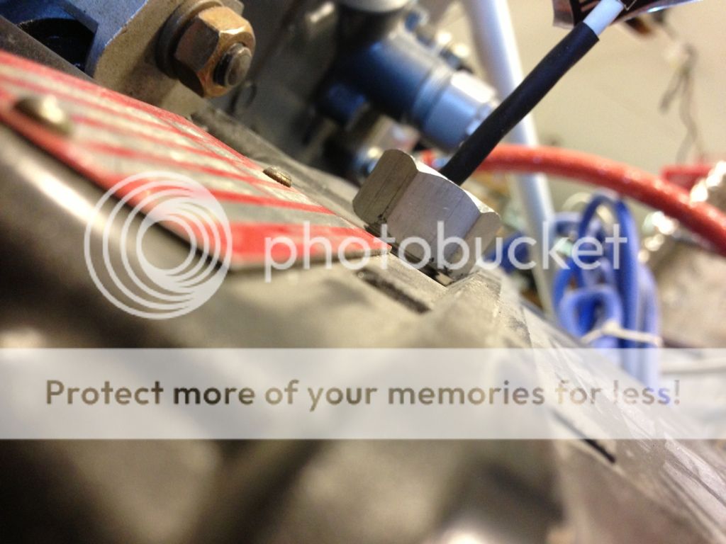
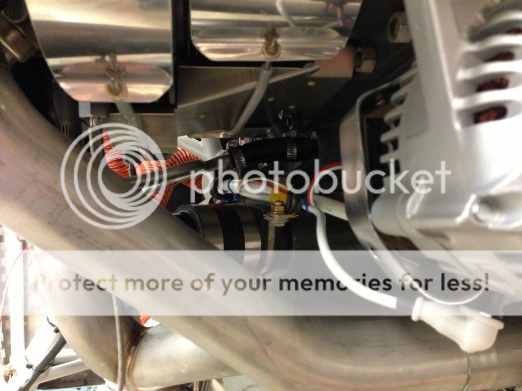
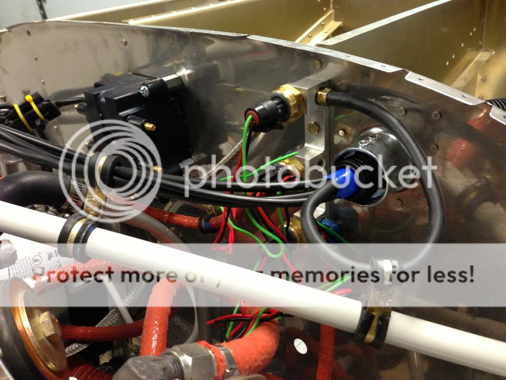
The stock harness ground was too short so I used butt splices and routed the grounds inside the conduit along with the manifold pressure hose.
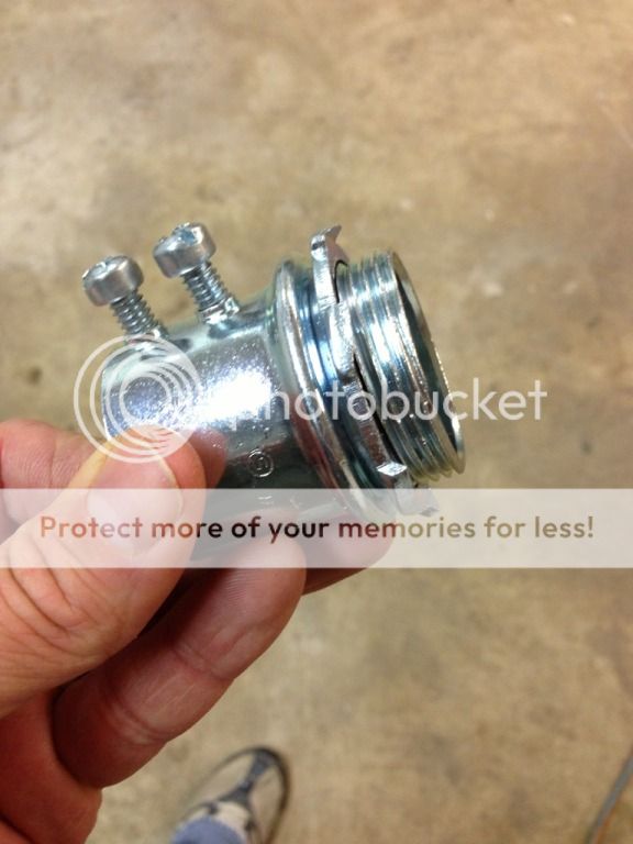
The kit comes with this...
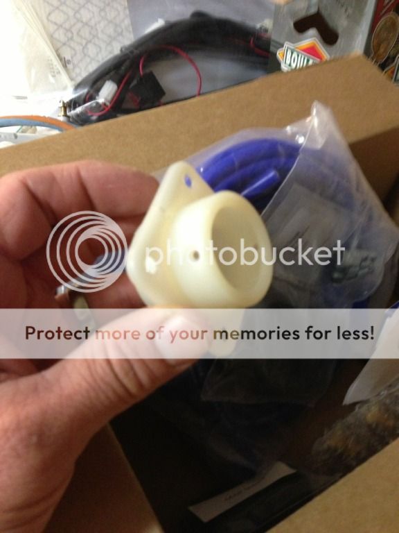
I used this instead with a .063 doubler, it is steel 1 3/4 inch inside diameter the connectors fit through and less than $2 at HD.
The black line on the right is for manifold pressure and joins the manifold block.
The other wires follow the engine mount. I still need to fire sleeve/seal between the steel fitting and the conduit.
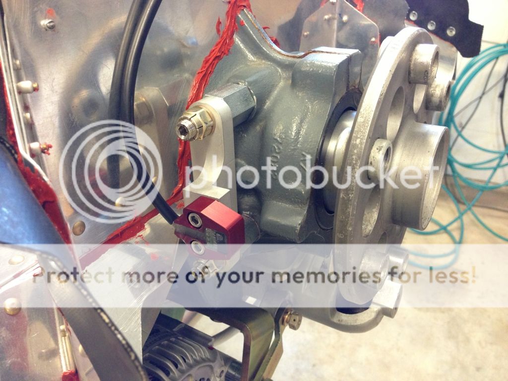
The right side of the engine where the coil and flywheel pickup snap in.
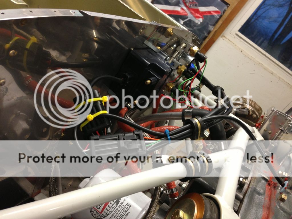
The connectors on the ECU, I still have to mount the manifold pressure sensor. There is +\- for the ECU and a+ for each coil output. I'm just using a single EFII but the wiring harness and ECU is set up to run dual ignition except for the extra coil and wires.
I'm running the power to the ECU through a switch, you could alternatively switch the power on the coil to enable/disable the EFII. A double pole switch could also be used to disable both ECU and Coil power simultaneously.
Manifold pressure sensor mounted.
The stock harness ground was too short so I used butt splices and routed the grounds inside the conduit along with the manifold pressure hose.
The kit comes with this...
I used this instead with a .063 doubler, it is steel 1 3/4 inch inside diameter the connectors fit through and less than $2 at HD.
The black line on the right is for manifold pressure and joins the manifold block.
The other wires follow the engine mount. I still need to fire sleeve/seal between the steel fitting and the conduit.
The right side of the engine where the coil and flywheel pickup snap in.
The connectors on the ECU, I still have to mount the manifold pressure sensor. There is +\- for the ECU and a+ for each coil output. I'm just using a single EFII but the wiring harness and ECU is set up to run dual ignition except for the extra coil and wires.
I'm running the power to the ECU through a switch, you could alternatively switch the power on the coil to enable/disable the EFII. A double pole switch could also be used to disable both ECU and Coil power simultaneously.
Manifold pressure sensor mounted.
I re-did the FWF wiring on the coil to better support the connectors.
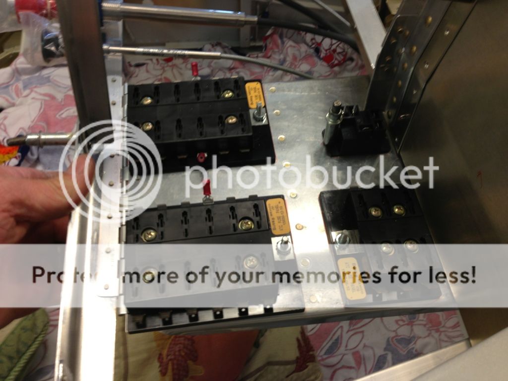
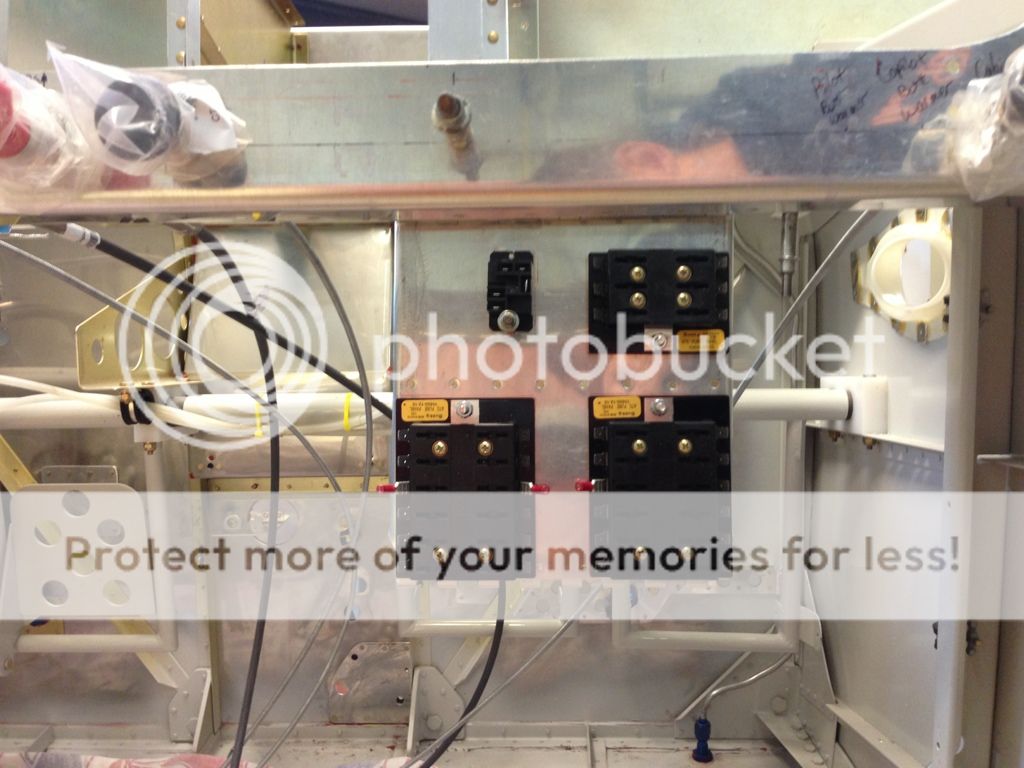
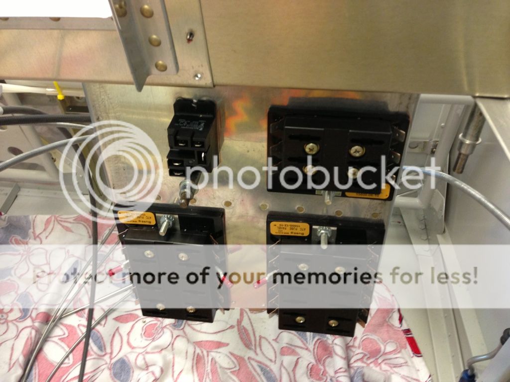
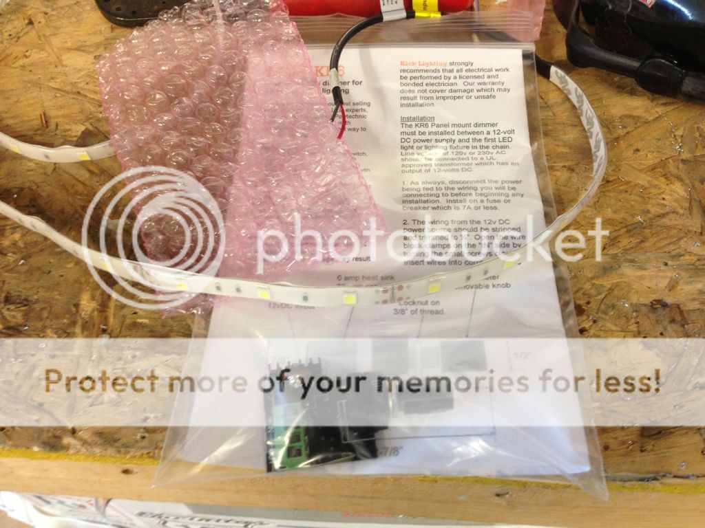
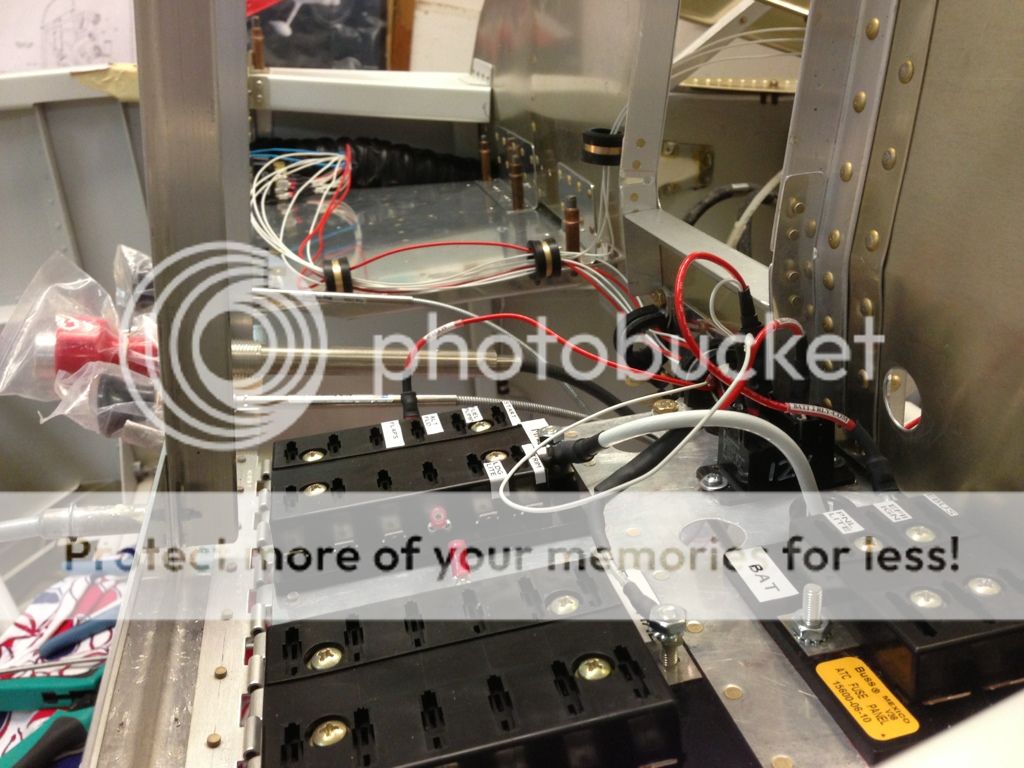
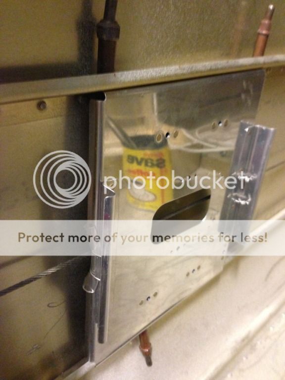
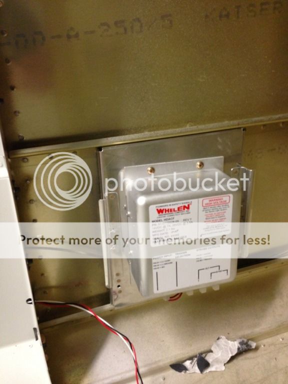
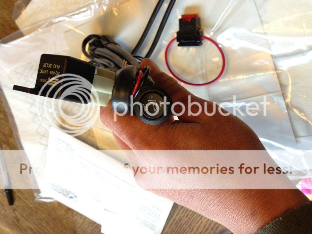
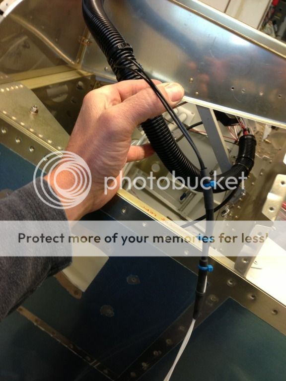
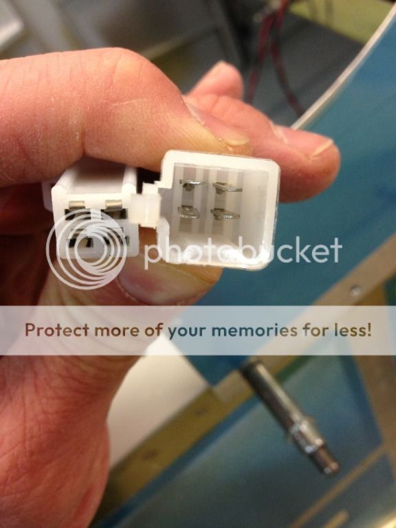
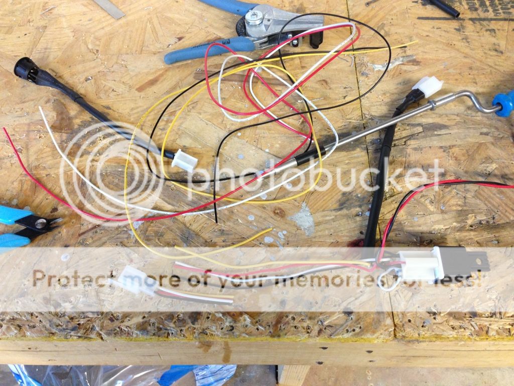
I also started on installing the wiring for the seat heaters, the stock wiring harness just didn't seem to work for me. If I used the existing harness I would have to bunch up several feet of wiring under the seatpan and armrest, (with the on/off button on the armrest) and run +/- wires to the seat pan from the fuse block. I decided to mount the relays to the backside of the subpanel and to start shortening/modifying the wiring harness.
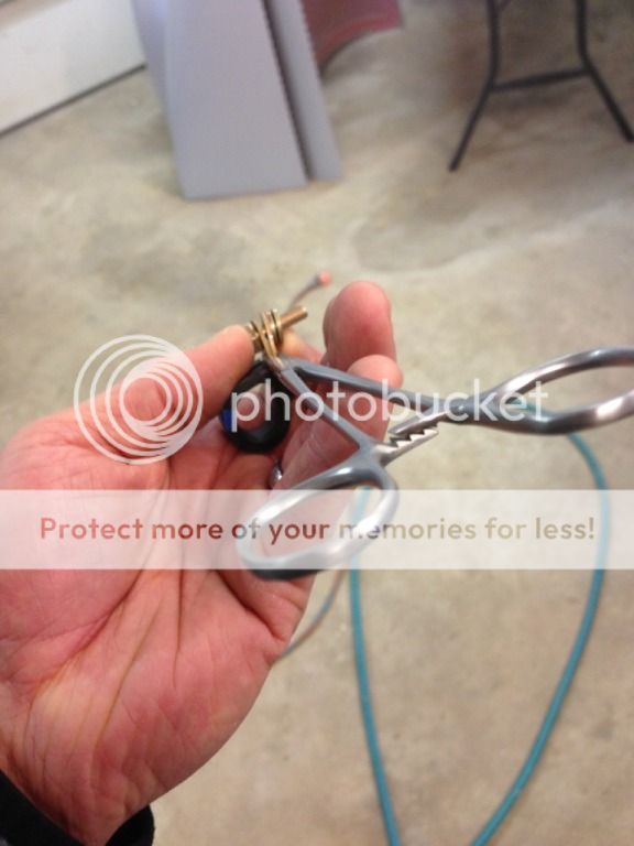
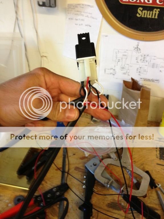
The harness as delivered, the white is the plug on the bottom of the relay, the left end above my thumb is the on/off button.
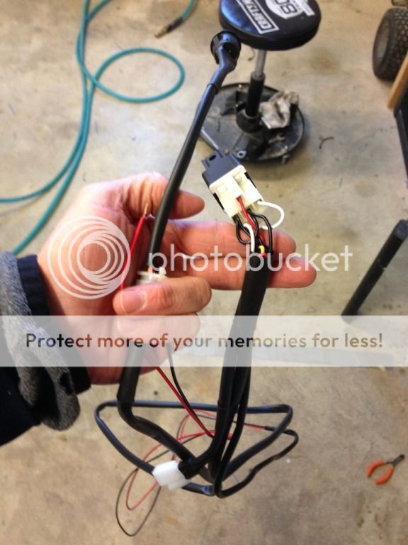
The protective sheath and +/- wires seperated.
I also started on installing the wiring for the seat heaters, the stock wiring harness just didn't seem to work for me. If I used the existing harness I would have to bunch up several feet of wiring under the seatpan and armrest, (with the on/off button on the armrest) and run +/- wires to the seat pan from the fuse block. I decided to mount the relays to the backside of the subpanel and to start shortening/modifying the wiring harness.
The harness as delivered, the white is the plug on the bottom of the relay, the left end above my thumb is the on/off button.
The protective sheath and +/- wires seperated.
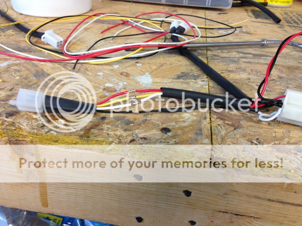
Shortening the butt heater wiring harness, the lose wire at the top of the photo was cut out. I tried but was unable to get new terminals which would have been easier/cleaner so I butt soldered them instead.
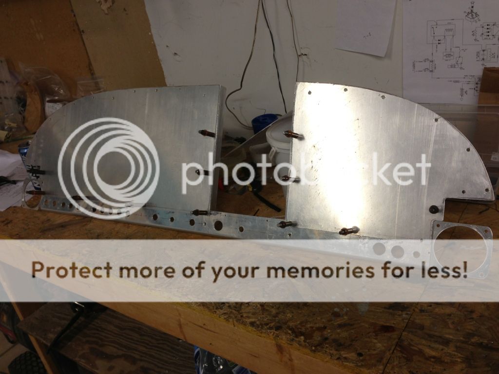
I also made some progress on my panel, I made the left and right panels flush with the inside edge of my radio stack angles. The angles are 6.35 inches apart for a little wiggle room, racks are supposed to be 6.33. I still haven't bought a bandsaw, kinda gratifying getting good results with a hacksaw and a file.
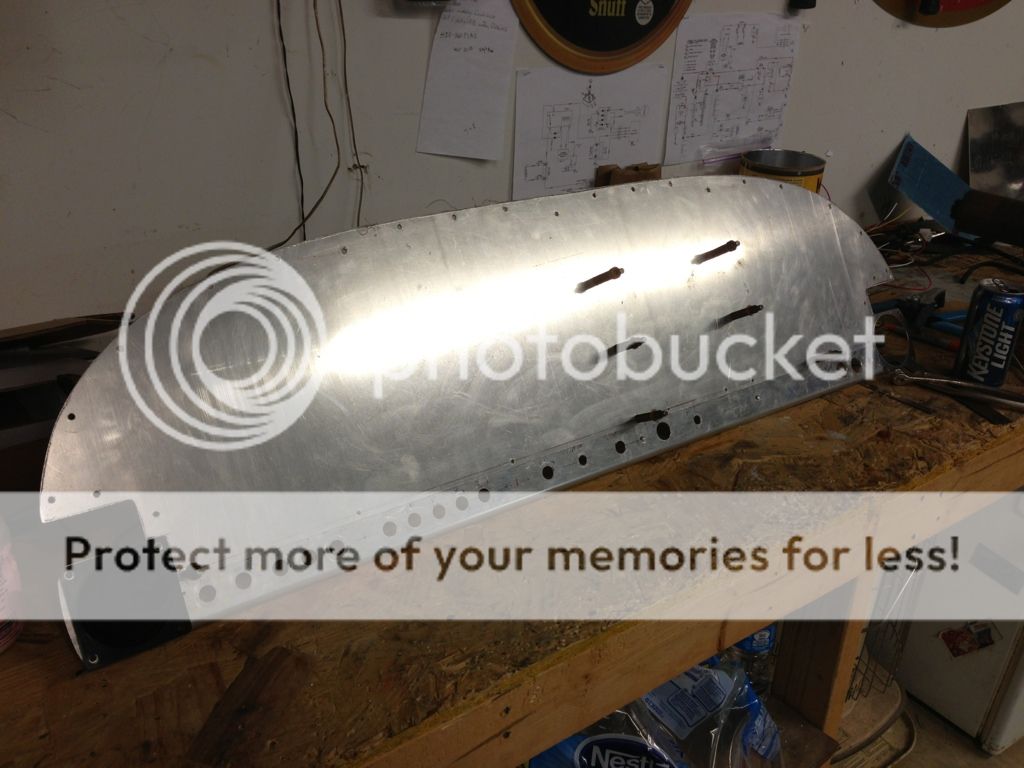
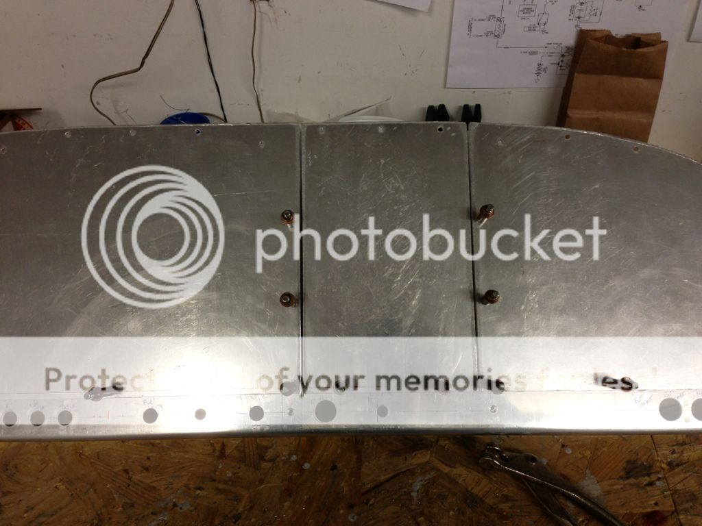
I also made some progress on my panel, I made the left and right panels flush with the inside edge of my radio stack angles. The angles are 6.35 inches apart for a little wiggle room, racks are supposed to be 6.33. I still haven't bought a bandsaw, kinda gratifying getting good results with a hacksaw and a file.

