What's new
Van's Air Force

Don't miss anything! Register now for full access to the definitive RV support community.

Fiberglass Rudder Bottom RV-7

I've been installing fiberglass tips on the empennage. I have progressed to the rudder bottom cap. I have a cap with provision for a tail light (I believe this is the standard cap now) and I am building the newer larger rudder design (2 skins and the AEX wedge).
At first glance, this bottom cap installation looked pretty easy. Score lines were in the gelcoat for trimming about a 1/2' along the lenghth of the cap, and for the cut-out for the rudder horn. Fortunately, before I started cutting, I checked the accuracy of the score lines and the fit of the cap.
It appears that overall length of the cap is about 5/8" shy of the length of the rudder botom (From beginning of the rolled leading edge to the trailing edge). If I line up the cap to match the trailing edge, the front edge is about 5/8" behind the rolled leading edge. When I position the cap in this manner the cut scorelines for the control horn are not correct.
I called Vans Tech support this morning (I haven't seen any posts about this issue on any of the builders websites). After discussing this with Ken, it sounds like the cap they are shipping is from the original rudder design. I was told to position the cap to allign with the trailing edge. The additional 5/8" space up front will allow extra clearance between the fuselage and rudder. Apparently there were clearance issues in this area? I have seen posts about clearance problems involving the cap on early 7's...
Can any one confirm their experiences with this part while building the new rudder design. Is this problem really a non issue?
 
The rudder bottom should fit evenly front to back and match the rolled leading edge. Mine does. I was going to send you some photos, but your settings do not allow me to do so. Also, you should have your VS attached to your fuselage and then set your rudder on the VS to make sure that the bottom is trimmed to match the bottom of the fuselage. Otherwise you may be too low or too high. Do not trust the score lines.
 
Rudder Bottom Cap

Ted,

The bottom cap fit the new rudder and the score marks were very close on my 7. Setback on the front is not a big deal since you may want to cut a big "smile" in it to clear tail light wiring, thereby creating a visual discontinuity between the metal and the cap that will tend to obscure the setback, which also is mostly hidden behind the fin. BUT, why start with a bum part and compromise? If Van's shipped a 6 cap, gently remind them that you're building a 7, and you'd like the correct part, please.

The clearance issue is on a tail dragger. The bottom cap interferes with the tail spring, so you must cut away the very bottom front and plug the hole with a lay up. Therefore, don't permanently install the bottom cap until you have the fuse to the point of being able to fit check. Also, make provision for screw threads to receive the fasteners retaining the tail light housing.

John Siebold
 
Fiberglass Rudder Botom RV-7

robertahegy said:
The rudder bottom should fit evenly front to back and match the rolled leading edge. Mine does. I was going to send you some photos, but your settings do not allow me to do so. Also, you should have your VS attached to your fuselage and then set your rudder on the VS to make sure that the bottom is trimmed to match the bottom of the fuselage. Otherwise you may be too low or too high. Do not trust the score lines.
Roberta, I'd like to see your pictures. I will tweak my settings so you can reply. Also please keep in mind that I am building the newer rudder which is larger. If your rudder is the early (1 piece folded skin) rudder design the cap would fit perfectly. Thanks for your help! ;)
 
Last edited:
Is it a good idea to order the lighting package (System 6 is what I plan on using) from Vans before attaching the rudder bottom so that the tail light can be fitted, or is it something that can easily be done later.
 
I ordered my system 6 early so I could fit the light and glue in some nuts for the mounting screws. It could be done later, just a little easier when you're only handling a small piece instead of the whole rudder. You can also set the lights in the wingtips as long as you have them.

I found it to be helpful having the FWF kit and finishing kit available, with my QB kit, right after the emp was completed. That way I could build in some of the things like lights and cables while I still had the best access. JMHO
 
Rudder lower cap pictures or dimensions

I am fitting the lower rudder cap on my -7 and as noted in the forums the lower front interferes with the tailwheel spring if you do not trim the top, did most people trim the the top of the fiberglass until the cap clears the spring? If so any approximate dimensions of how much to trim off? I assume it cannot be a parallel cut as the tail strobe light limits how much can be taken off the rear. How much clearance gap should I leave to account for spring travel?
Thanks
 
I cut mine so that I had about 3/4" clearance from the tailspring. Cut it on an angle so that nothing is cut off at the aft end.
 
One question.

Are you building a -7 or a -7A?

If you are building a -7, wait to fit the cap until the VS and rudder are on the fuesleage and the tail spring is in.

The lines you see in the rudder came from a -7A and if you were to trim it there, the rudder bottom would interfer with the tailwheel spring.

Take a look at this page and scroll down to the 5/26/06 entry for details.
 
I found mine fit best with a new line drawn approx 3/8ths below the line at the front tappering back to the orginal line at the trailling edge. If you have the fin and tail wheel on you can just work a bit off at a time

Peter
 
Last edited:
Thanks for feedback

Think I have it all figured out now and will cut at an angle as most have done to clear the tailwheel spring (thanks Bill for the pictures). Next trick is figuring out where to run the wires to the rear strobe/light combo, seems like multiple approaches have been taken.
 
I have a problem with the angle of the tailwheel fork pointing aft too much and the gear spring too close to the bottom of the rudder cap. It has been smashed twice. I re checked the build sheets and found it was installed as per plans. My question is that I want to raise the forward bulkhead attach weldement to lower the spring and change the angle of the fork. Any pros or cons to that idea?
 
I have a problem with the angle of the tailwheel fork pointing aft too much and the gear spring too close to the bottom of the rudder cap. It has been smashed twice. I re checked the build sheets and found it was installed as per plans. My question is that I want to raise the forward bulkhead attach weldement to lower the spring and change the angle of the fork. Any pros or cons to that idea?

Have you considered re-shaping the rudder fairing instead? Getting to the bulkhead to change the attach points, which would possibly result in either repairs to the bulkhead or replacement of same due to new holes being to close to old, would be a substantial amount of work with a risk of additional damage due to all the rivets that have to come out, etc. Fiberglass work on the other hand, is pretty easy.
 
What would you recommend for a fix the angle of the "king Pin"?

The forward weldement is attached with only 2 bolts. It would not be hard to raise it but I wonder how it would effect the rear weldement. Or would it?
 
This is really a no brainer. Moving the spring weldment seems like a solution looking for a problem. Just trim the fiberglass anywhere it is likely to rub and reshape. Or, if you want to keep the same profile of the rudder tip, buy a new one and install it so that the forward edge sits higher. Even if you try to reposition the weldment on the fwd bulkhead and are able to drill new holes with sufficient edge distance, your holes on the aft bulkhead, that also go through the spar of the VS, will no longer line up at the same angle.

The reason your tip may stick down too far is that the builder followed the plans for nosewheel plane and installed it prior to having the plane on the tailgear.
 
Last edited:
I just put in new bulkheads & the tailwheel spring & mount. Changing from an A model. As suggested, reshape the fiberglass fairing if required. Moving the tailspring mount is a bad idea. Those two 1/4" bolts attach to the angled vertical bars that hold the horizontal stab to the tail. To get proper distance between bolt holes, the mount would have to be raised much too high. It would also require shims, as the surface of the mount & bulkhead would be out of alignment. It would also require shims on the aft bulkheads, as the mount weldment would no longer sit flat against the surface.

So far, my fiberglass fairing, misses the tailspring, but not by much. I may end up reshaping the fiberglass also. But............much easier & stronger, than attempting to change anything else........once they've been drilled.

L.Adamson
 
Think I have it all figured out now and will cut at an angle as most have done to clear the tailwheel spring (thanks Bill for the pictures). Next trick is figuring out where to run the wires to the rear strobe/light combo, seems like multiple approaches have been taken.

For clearance, double check how the spring sits with weight on the tail. (You could put the tailwheel on a scale and add weight until the scale reads 70#.)
 
What would you recommend for a fix the angle of the "king Pin"?

The forward weldement is attached with only 2 bolts. It would not be hard to raise it but I wonder how it would effect the rear weldement. Or would it?

By "kingpin" do you mean the post on the tailwheel fork? If the tailwheel spring is straight and the weldment is installed correctly (easy to check if you have the plans) then the angle of the fork post should be ok.

In any case, the forward and aft plates on the tailwheel mount weldment are parallel, assuming that it's not bent. If you try to raise the front, you'll have to make tapered shims for both fore and aft mounting plates, since they'll no longer be parallel to their respective bulkheads. That's in addition to the issues previously raised.

At this point, it might be best if you could post a photo or two of your setup. That would make it easier to offer constructive advice.
 
I am surprised by the replys that are more concerned about the aesthetics than the mechanics. I only mentioned the rudder fairing to give an idea where things were.
I went back and looked at pictures that were taken of the plane when it was finished. The "kingpin" was vertical then. Now it is not. Something has to be bent but I can not see it. I want to put it back to the original position but dont see what needs to be fixed. I dont think repositioning the forward bracket is the fix but a band-aid. I pulled the tailwheel strut out and rolled it on the flat surface. It's not bent. I cant see any damage to the fork holding devise thing.

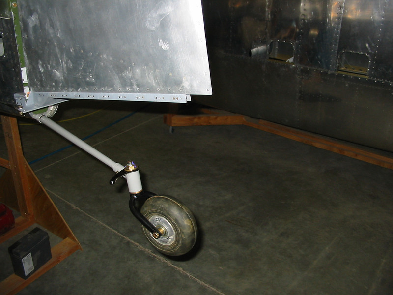
No concern about aesthetics on my part. Unfortunately I don't have a good shot of my tailwheel fork installed, but the pivot pin (or king pin) tilts forward at the top. You can sort of see it in the photo below.

i-NDHLLPh-L.jpg


My comments stem from having installed the tailwheel weldment in my own fuselage. If something is truly bent, it would have to be one of the two aft bulkheads, or the fuselage would have to be buckled. If you are convinced that something is bent, you'll want to pull the horizontal & vertical stabilizers to check.

It's common for the rudder fairing on these things to contact the tailwheel spring. You have to tuck the fairing up higher than the plans would indicate to get it to clear. Hence the comments about modifying the fairing.
 
Back
Top