

Bill_H
Well Known Member
I just finished my "hood scoop" mod to substantially increase airflow to the RV12 voltage regulator and NOT moving it inside the cabin. The concern is that overheating of the VR is most likely to be occurring during ground operations, when the engine rpm is low, airflow to the VR is low, and VR output may be high.
This mod is done as follows. I did NOT want to relocate the VR inside the cabin. Note that I also installed the Bender Baffle cabin heating modification so this had to be compatible.
This is the basic design of the scoop, which goes in the radiator duct.
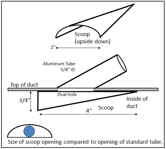
You need both a scoop and a piece of 5/8" ID aluminum tubing. I chose that because I wanted to reuse the existing corrugated tubing supplying air to the VR.
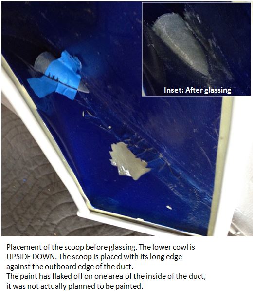
The location of the scoop has to be far enough forward to not interfere with the Bender Baffle. In this pic, the lower cowl is UPSIDE DOWN and you are looking in from the square radiator opening.
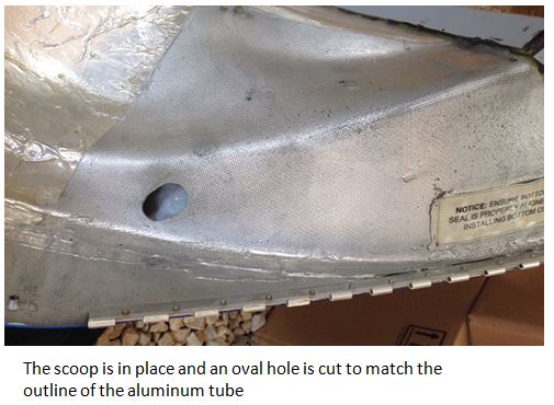
With the scoop glassed in, I cut a hole in the top of the duct that matched the oval opening of the cut tube, then glassed in that tube. I had more than enough leftover corrugated tubing from the original installation to do all this. This picture is looking DOWN on the cowl, rightside up. To the left is FORWARD. on the right you can just see the corner of the square gasketing where the duct opening mates to the radiator. That oval hole is adjacent to the front of the forward pilot-side cylinder on the engine.
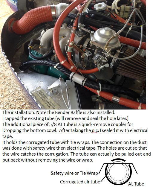
So here is the installation. The aluminum tube glassed to the duct is wrapped in electrical tape to seal the corrugated hose. Note the quick-remove coupler in the middle of the corrugated hose going to the VR - for removing the bottom cowl. The diagram shows how the corrugated tube is held in place by either safety wire or narrow tie wraps through holes cut in the aluminum outer tube. (I did not think of this - I saw it done by Joe Gores).
So, it "should" be better. After all, the existing setup has a narrow round opening that is at a right angle to the airflow it is trying to "catch." On the ground, that airflow itself comes from the SCATT tube opening which is at the very root of the prop - an area that does not produce much thrust. I had previously done a test with a dowel and yarn to prove to myself that there was a LOT of airflow at idle RPM going through the radiator part of the duct. But, how to prove that the scoop works?
Here is the setup.
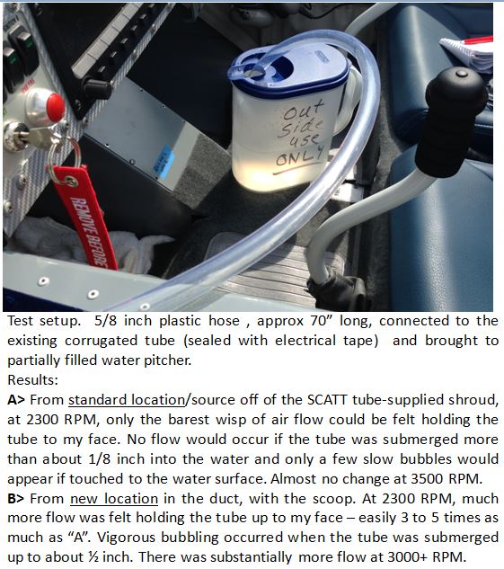
I tested both the original source and the scoop source by connecting the tubing from each to a ~70 inch piece of clear plastic tubing run into the cockpit. I tested on the ground with the engine at 2300 RPM (typical warmup idle) and at 3500 rpm. For each case I let the tubing blow on my face and also into the water container, where I could see bubbles if I submerged the tube. (I tried to take pictures but they did not come out well. I was alone.) Now yes, the 70" of tubing does increase the resistance and the flow at my face will be less than would be at the VR. But that restriction is the same for both cases.
The RESULTS!
A> From the standard location/source off of the SCATT tube-supplied shroud, at 2300 RPM, only the barest wisp of air flow could be felt holding the tube to my face! No flow would occur if the tube was submerged more than about 1/8 inch into the water, and only a few slow bubbles would appear if the tube was held touching the water's surface. There was almost no change change at 3500 RPM.
This seems to verify that cooling of the VR during ground ops with the standard setup is marginal.
B> From the new location of the scoop in the duct. At 2300 RPM, much more flow was felt when holding the tube up to my face – easily 3 to 5 times as much as “A”. Vigorous bubbling occurred when the tube was submerged up to about ½ inch. There was also substantially more flow at 3000+ RPM.
So I am calling this enough evidence for proof.
This mod is done as follows. I did NOT want to relocate the VR inside the cabin. Note that I also installed the Bender Baffle cabin heating modification so this had to be compatible.
This is the basic design of the scoop, which goes in the radiator duct.
You need both a scoop and a piece of 5/8" ID aluminum tubing. I chose that because I wanted to reuse the existing corrugated tubing supplying air to the VR.
The location of the scoop has to be far enough forward to not interfere with the Bender Baffle. In this pic, the lower cowl is UPSIDE DOWN and you are looking in from the square radiator opening.
With the scoop glassed in, I cut a hole in the top of the duct that matched the oval opening of the cut tube, then glassed in that tube. I had more than enough leftover corrugated tubing from the original installation to do all this. This picture is looking DOWN on the cowl, rightside up. To the left is FORWARD. on the right you can just see the corner of the square gasketing where the duct opening mates to the radiator. That oval hole is adjacent to the front of the forward pilot-side cylinder on the engine.
So here is the installation. The aluminum tube glassed to the duct is wrapped in electrical tape to seal the corrugated hose. Note the quick-remove coupler in the middle of the corrugated hose going to the VR - for removing the bottom cowl. The diagram shows how the corrugated tube is held in place by either safety wire or narrow tie wraps through holes cut in the aluminum outer tube. (I did not think of this - I saw it done by Joe Gores).
So, it "should" be better. After all, the existing setup has a narrow round opening that is at a right angle to the airflow it is trying to "catch." On the ground, that airflow itself comes from the SCATT tube opening which is at the very root of the prop - an area that does not produce much thrust. I had previously done a test with a dowel and yarn to prove to myself that there was a LOT of airflow at idle RPM going through the radiator part of the duct. But, how to prove that the scoop works?
Here is the setup.
I tested both the original source and the scoop source by connecting the tubing from each to a ~70 inch piece of clear plastic tubing run into the cockpit. I tested on the ground with the engine at 2300 RPM (typical warmup idle) and at 3500 rpm. For each case I let the tubing blow on my face and also into the water container, where I could see bubbles if I submerged the tube. (I tried to take pictures but they did not come out well. I was alone.) Now yes, the 70" of tubing does increase the resistance and the flow at my face will be less than would be at the VR. But that restriction is the same for both cases.
The RESULTS!
A> From the standard location/source off of the SCATT tube-supplied shroud, at 2300 RPM, only the barest wisp of air flow could be felt holding the tube to my face! No flow would occur if the tube was submerged more than about 1/8 inch into the water, and only a few slow bubbles would appear if the tube was held touching the water's surface. There was almost no change change at 3500 RPM.
This seems to verify that cooling of the VR during ground ops with the standard setup is marginal.
B> From the new location of the scoop in the duct. At 2300 RPM, much more flow was felt when holding the tube up to my face – easily 3 to 5 times as much as “A”. Vigorous bubbling occurred when the tube was submerged up to about ½ inch. There was also substantially more flow at 3000+ RPM.
So I am calling this enough evidence for proof.
Last edited:
")

