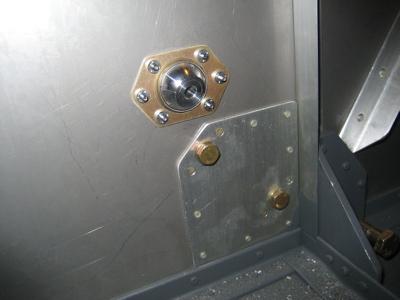
Okay, here are my FW eyeball positions, measured as best I'm able on a mostly-finished firewall (which is not terribly precise). Should hopefully be near enough to let you compare them to the plans positions. All locations refer to the center of the hole. Also note that my airplane is a taildragger so the geometry of our respective engine mounts will be different.
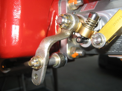
Throttle is about 5 1/4" up from the bottom skin, and about 3 1/4" inboard from the rivets that attach the F-601N-R vertical stiffener. My notes say I moved it 1/4" up and 1/4" inboard from the plans location in order to clear the existing doubler for the carbureted fuel pump.
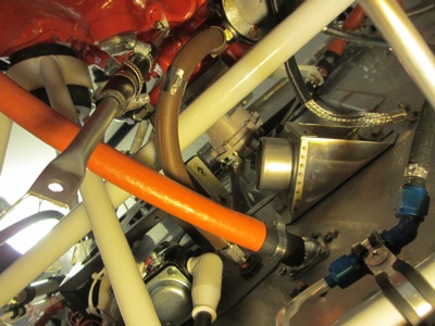
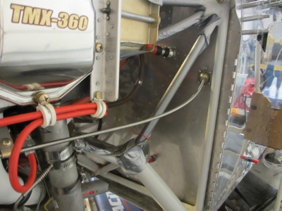
Beware of conflicts with the fuel hose, and also note that the plans location for the fuel hose should really be another 1/4" inboard to give more clearance for the starter solenoid. Additionally, I later had a tricky situation with the throttle cable versus the exhaust pipe hangers where the available clearance would have been a little better if I had moved the throttle cable hole straight up instead of up-and-in:
I recall having issues with the throttle cable, in that it is tricky to get it all the way from the back of the engine to the front without touching the exhaust pipes or fouling on the corner of the oil sump, all while ensuring sufficient travel from stop to stop. Even when it's all correct the clearances are none too generous.
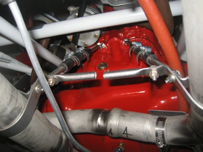
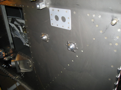
Mixture is about 4 1/2" down from the rivets that attach the F-601L angle that goes across the top of the firewall, and about 11 1/2" in from the fuselage side skin (port side). No real issues with the firewall location of the mixture cable (routing it around to the front of the engine is a different story).
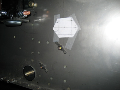
Prop is at the same elevation as the mixture cable, and about 8 1/4" in from the fuselage side skin (port side). On this I would recommend choosing a lateral position that gets the prop cable as far outboard as possible while still remaining inboard of the diagonal fuselage stiffener (F-601D-L). Or to put it another way, tuck it right up against the inboard of the diagonal stiffener, remembering to provide clearance for the eyeball screws. I believe the "no!" hole location in the photo below is the plans position, which I think would be tricky to make work without hitting the left magneto.
Alternate Air cable is in pretty much the same location used by Steve in the post above. This ends up being pretty precisely located in order to clear the engine mount, so I would recommend waiting till the mount is fitted to drill this one. For reference, mine is about 2 1/4" in from the fuselage side skin, and 6 1/4" down from the upper-left engine mount bolt.
Hope that helps.
good luck,
- Matt


")