What's new
Van's Air Force

Don't miss anything! Register now for full access to the definitive RV support community.

Antisplat Aero Crankcase Vacuum Valve Fitting Broken at Weld

Gash

Well Known Member
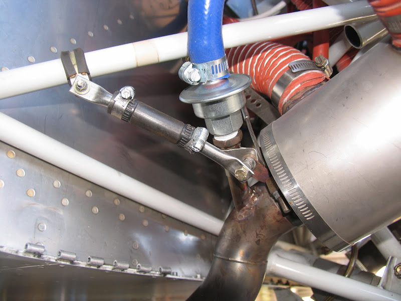
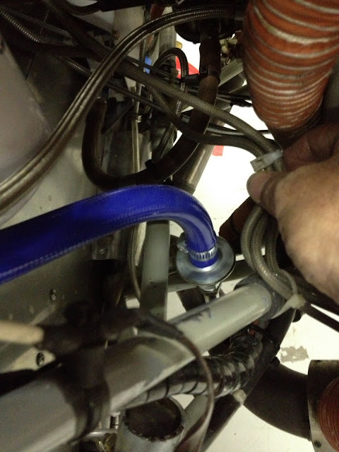
I have 55 hours on my Antisplat Aero Oil Separator and have been extremely pleased with it. My belly is literally spotless. I purchased and installed the full ASA Oil Separator setup, including the separator, install kit and crankcase vacuum valve with weld in tube fitting.

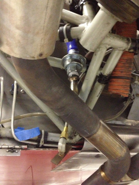
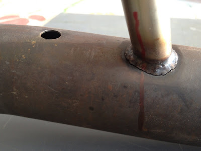
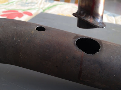
With the cowl off today, I noticed this:

BrokenWeldInFitting_zpsc265a607.jpg


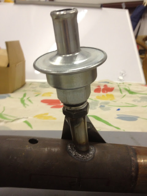
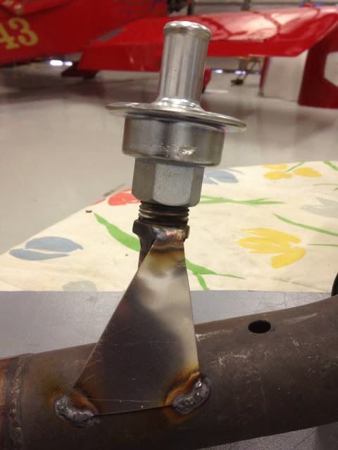
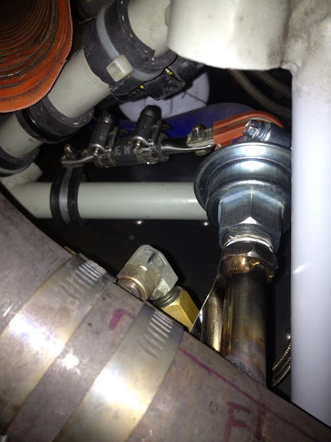
It looks like 55 hours of engine vibration was enough to break the weld on the #3 exhaust pipe. The fitting is just resting in the hole and can be pulled up and wiggled around. The weld is completely broken. I had the welding done at a reputable place that knows how to do stainless steel exhaust jobs.

I have four questions if anybody could help me out:

1) Is it safe to fly the airplane on a short flight, for example, to ferry it to someplace where I can get the exhaust pipe and vacuum fitting repaired? How about longer flights while waiting to get this fixed?

2) Is there a better way to install this fitting the next time around? I don't want to keep repairing welds that break from temperature and vibration issues. Would it be better to attach the fitting with a nut? If so, how would I avoid exhaust leaks at such a connection?

3) If welding is the only way to repair, what type of place should I take it to next time for a better weld? Any specific recommendations by name?

4) Finally, this is a Vetterman 4-pipe exhaust. Is it possible to disconnect the last section of the pipe at the joint, or do I need to drop the whole pipe and get a new one? I have no experience with exhaust repairs.

Thank you in advance for any suggestions you can provide!
 
.... We have never seen this before with several thousand out there! I am wondering if it was welded with the proper rod. Vetterman does these all the time with no issues, and we have airplanes with thousands of hours on the systems. At any rate, If you can send it (the pipe) to us we will would be more than happy to correct this for you at no cost to you. Please give me a call if we can be of service to you. Allan ...:confused:
 
Thank you Allan! You are the heart and soul of experimental aviation. I figured it had to be a welding thing. I'll send you the pipe and let you have a crack at it (pun intended!)

By the way, I sent you a voicemail and email earlier today too--apologies for the over-communication. Have a great weekend!
 
I have four questions if anybody could help me out:


2) Is there a better way to install this fitting the next time around? I don't want to keep repairing welds that break from temperature and vibration issues.

Thank you in advance for any suggestions you can provide!

This is the prompt I needed to get "image posting qualified" Karl. I'll try to get you a photo of what I think is a good fix. Bracing the tube is good.

Later....
 
I used this product from Jegs - pn: 555-30739 to provide extra support for the check valve. I only have about 15 hours on it, so it has yet to prove worthwhile.
 
We have welded many of these in and we always add a doubler patch that is about the size of a silver dollar at the base of the pipe where it is welded on, to prevent any cracking issues.
 
I like Dan's idea regarding a clamp systemhttp://www.vansairforce.com/community/showpost.php?p=722195&postcount=13

If you then put a short piece of hose on tubing to the exhaust, then the valve, and then the tubing to the oil separator this would take away some of the stress to that weld/tubing. Although the valve is not heavy, the "moment" is multiplied by the length of rigid tubing. Isolating the valve, using the original hose, would greatly reduce the stress. Of course the hose would have to be able to stand the heat at that location. This might even make it easier to inspect the valve as removal would simply be two hose clamps.
Just a thought.
 
If you then put a short piece of hose on tubing to the exhaust, then the valve, and then the tubing to the oil separator this would take away some of the stress to that weld/tubing. Although the valve is not heavy, the "moment" is multiplied by the length of rigid tubing. Isolating the valve, using the original hose, would greatly reduce the stress.

I really wanted to do that, but couldn't find a suitable flex tube which I thought might withstand the heat. Kicked around the idea of a SS braid/teflon like we use for smoke lines, but figured in a large diameter and short length it would be as stiff as rigid tube. Any ideas?
 
Another Fitting Version

Hi Gents,

I'd like to load a photo of my installation. I copied photos posted by DanH on another thread showing his heat shield. Then took my exhaust pipe (Vetterman 4 pipe) to my machinist buddy who came up with this.

http://s1318.photobucket.com/user/D...3&page=1&_suid=136595587337106976210981307573

(I don't have time to wrestle with getting this photo posting, I got to go flying:D Can anyone get this online??? Sorry )

But, I think this is a good setup as it braces the tube and provides some heat shielding as per DanH.

Cheers,
 
This looks like a neat system, but I wonder what the failure modes are.

For example: What happens when the check valve fails open? Would we get large positive pressures and associated oil loss in the crankcase?
 
Good ideas!

For the 10, the bracket is already in place and all that was needed was a stainless steel clamp tying into it.
 
Oh Thank you mucho Brian, I'm off to the airport. Will come back & study the photo uploading some more.

I really appreciate it. :D
 
I like Dan's idea regarding a clamp systemhttp://www.vansairforce.com/community/showpost.php?p=722195&postcount=13

If you then put a short piece of hose on tubing to the exhaust, then the valve, and then the tubing to the oil separator this would take away some of the stress to that weld/tubing. Although the valve is not heavy, the "moment" is multiplied by the length of rigid tubing. Isolating the valve, using the original hose, would greatly reduce the stress. Of course the hose would have to be able to stand the heat at that location. This might even make it easier to inspect the valve as removal would simply be two hose clamps.
Just a thought.

I really wanted to do that, but couldn't find a suitable flex tube which I thought might withstand the heat. Kicked around the idea of a SS braid/teflon like we use for smoke lines, but figured in a large diameter and short length it would be as stiff as rigid tube. Any ideas?

I also like Dan's clamping idea and Tom's tubing isolator. I just did my first flight with Alan's separator and crankcase vent valve, along with a few other winter mods:
IMG_0302_2.jpg


Had to work in a tight space with a few "bracketing" constraints (engine mount and smoke oil injector). Still contemplating support methods, and the gussets shown are interesting.

On the flex hose...Dan, your idea may work OK. I just installed a 4" length of fire-sleeved, braided hose as part of an EFII boost pump install, and it flexed to a slight curve nicely. As you mentioned, a larger diameter and shorter hose may not bend much, but I think it will have enough give to provide relief to the weld. Perhaps shortening the welded tube and adding the flex hose would be workable, and not put the valve too far away from the ex pipe to diminish the negative pressure applied to the valve. How far upstream do you figure the valve will maintain its full effect?

Alan, you mentioned very few failures are seen at the weld. In your experience, do the majority of the installations have a support bracket installed?

(PS: Dan, OT, but do recognize one of your previous recommendations to me in the background? Hint, part of my version of a shrinking exit and exit flow mod, with much inspiration from you...and Tom! Collecting data now for a report to follow...thanks in advance!! ;)

Cheers,
Bob
 
Antisplat Aero Fixed It!

I just got my repaired exhaust back from Allan at Antisplat Aero. Here are my observations.

1. The cracked weld wasn't Antisplat Aero's fault--it was my original welder's mistake that caused the problem. Although the original weld looked nice, it was done too hot which caused weakness in the metal. Despite this, Allan offered to repair it at no cost. I am very happy with his kindness and customer service.

2. The new welding looks beautiful and I'm sure it will outlast the airplane. Allan shortened the length of the weld-in tube since it doesn't need to be so long (too much length amplifies vibration effects, of course). He also welded on a couple of gussets which look nice and sturdy. I spoke with Allan on the phone today, and he explained that *this* is the right way to do it. See the photos below for the "approved solution" of how the installation should look.

3. Finally, I tried to order one of their axle wrenches earlier this week to put in with the return shipment, but they wouldn't let me pay for it! Yep, Allan threw in one of his wrenches for free. Wow!

Thank you Allan and James for the excellent repair, quick turnaround, customer service and generosity. I am a loyal customer for life! Now I'm looking forward to the RV-8 gust lock--that will be my next purchase.

(I'm going to put this in a separate thread too so that it'll help others more easily find the photos showing how Allan welded in the tube with gussets).

IMG_0002_zps4e19bcc3.jpg


IMG_0005_zpsace1dc1b.jpg
 
Last edited:
Although the original weld looked nice, it was done too hot which caused weakness in the metal.

Although there are several possible mistakes, "too hot" isn't likely to be one of them.

Allan shortened the length of the weld-in tube since it doesn't need to be so long (too much length amplifies vibration effects, of course). He also welded on a couple of gussets which look nice and sturdy. I spoke with Allan on the phone today, and he explained that *this* is the right way to do it. See the photos below for the "approved solution" of how the installation should look.

Shortening the tube will also raise valve temperature.

Would you or Allan care to explain why this gusset arrangement is the right way?
 
On the gussets, I shall defer to Allan on that question, as it's his handiwork. As for the length of the tube as shipped, Allan said that it's sent intentionally long to allow end users to fit the valve/hose in tight or awkward locations. However, it is certainly not necessary to use the entire length of the tube. I don't know what the minimum acceptable tube length is though.
 
Although there are several possible mistakes, "too hot" isn't likely to be one of them

Anyone here who has any experience at all with tig welding stainless steel will know that "too hot" is most likely "the problem". If it's not done properly on the first pass at the right amperage or trying to go over it to make it pretty or being too slow moving the tungsten will overheat the metal and crystallize it and make it extremely brittle and prone to cracking.
 
Well, in the category of "shoulda done that first", while "contemplating" a support mechanism for the crankcase vent valve, I flew 4 test hops to evaluate this system and a few other performance mods I've been working on.

Removing the cowl after the latest test hop revealed a cracked weld at the vent valve insertion. Crack was 360 degrees resulting in a "removable" vent valve. Obviously should have had some support...now planning a re-weld, to include a gusset, and a support bracket. I have a question for the brain trust on the latter below...first a couple pics:

IMG_0578_2.jpg


IMG_0579_2.jpg


The weld was done by a very experienced TIG welder and master machinist, and he didn't think too hot, too cold or bad weld in our case (and he's a friend with no skin in the game other than helping me out). He feels a gusset, and more importantly a brace, will be the keys to success. Plan is to add the gusset approximately along the red line in the pics above. Allan, I'd also be interested in why your weld is more appropriate than a triangular gusset as shown in others' photos. Not drawing swords at all, just want to do it right! The product is great! :)

As for the brace, my current thought, based on the geometry and proximity of my engine mount in this area, is to connect one adel clamp to the blue hose just above the worm clamp at the top of the valve (just above the top of the valve), then connect it to another adel clamp that will go around the engine mount just aft of the blue hose (left of it in the pic below). My thought is the hose will flex a bit, so the connection will not pull at the valve (and the weld), but it will stabilize the valve.
IMG_0300_2.jpg


Another angle showing the limited space:
IMG_0302_2.jpg


For those following this thread, do you see any issues with this method? An alternative would be to fab a brace as Ernst did (one end on the lower part of the valve, one on the engine mount, flexible hose in the middle), though I may have mount geometry issues to accomplish this...working on it! Thoughts and input most appreciated.

Dan, I did a search to see if I could find a pic of how yours is braced, but couldn't find one. If you've posted one, can you provide a vector to it, or maybe post one when you have a chance. Thx...much appreciated.

Thanks much!!

Cheers,
Bob
 
Last edited:
He feels a gusset, and more importantly a brace, will be the keys to success. Plan is to add the gusset approximately along the red line in the pics above. Allan, I'd also be interested in why your weld is more appropriate than a triangular gusset as shown in others' photos.

Four triangular gussets seem like an obvious solution, but they're not optimum as they concentrate stress at the tips of the gussets. In this example the gussets on the top centerline of the exhaust pipe are particularly bad. Their tips work the exhaust pipe like the skin of a drum. Can you say fatigue?

wiavwz.jpg


A tent gusset would be much better structurally (and double as a radiant heat shield). Note all load is now applied to the exhaust pipe in shear, tangent to the pipe.

ed6xi.jpg


Allan's gusset arrangement in Juvat's photos is a minimalist approach to the same concept. Deal's brace is the right concept too, although it would be a little stiffer with straight legs.

Dan, I did a search to see if I could find a pic of how yours is braced, but couldn't find one.

Bob, it's not braced, at least not at this time. Consider a few details.

The vibratory acceleration is increased by increasing the distance from the rotational center of the engine mass. Put another way, a distant tailpipe flails around with more vigor than any point closer to the engine center. Mine isn't welded into a tailpipe, but rather in the #4 pipe just inboard of the first bend.

The tap tube isn't very long.

It's not welded with a little bitty bead, meaning the diameter of the weld root at the exhaust pipe is larger, reducing stress. I tried to avoid full penetration, as the inside of the exhaust pipe is covered with carbon. Regardless, the pipe was sealed and back-gassed.

Will it stay? I dunno. We'll find out.

1zoud92.jpg
 
Thanks very much Dan! When I showed Dave (my hot rod machinist buddy) the pictures of triangular gussets, he pointed to exactly the same points you did as weak points that would eventually fail. I see your solution and how it relates to Allan's...good discussion and examples...thanks! I will show him your pics today...will definitely help forge our solution (pun intended). ;)

Understood on the pendulum-like effect of being further outboard, as in my case. With the hose connected at the top, and the engine and pipes doing their rocking, I was definitely putting a lot of stress on the connection. And both Dan and allbee...concur with you on the weld thickness...that pic and discussion will help as well!

Time to go get a welder's mask on! Thanks again!

Cheers
Bob
 
Last edited:
Here's the solution we came up with after reviewing the various pics and discussion, and trying a few different ideas in the tight area I'm working in. Ended up with a hybrid, combining a few of the great ideas discussed here.

Welded the valve's stem back in place, then welded a triangular gusset, with the base tangent to the pipe as Dan suggested, and the top welded to the bung where the valve screws in.

IMG_0585.jpg


IMG_0587.jpg


Went with one gusset on the aft side of the assembly, because space on the front was pinched between the engine mount and the smoke oil injector and associated clamps. Would have preferred both sides being gusseted, but added a support bar between adels to support the structure, somewhat similar the picture Ernst posted. Captured the top of the valve just above the blue hose's clamp (the orange adel), and then to the engine mount (black adel). Stainless tube was used to make the bracket arms, and hose ties them together (typical exhaust hanger methodology).

IMG_0589.jpg


A bit of a knife fight in a phone booth in there, but hopefully it will be secure, and will help prevent another failure around the weld.

Thanks again for the discussion and recommendations!

Cheers,
Bob
 
Bob, couple comments.

Ditch the adels. Bad idea.

The single-sided thin sheet gusset will flex when loaded in compression. Flexing will defeat the welds. Bent flanges on the long edges of the gusset would be the minimum.

Ok, so space constraints are forcing bad structure. Back up, start over. For example, you could do the whole thing just like the smoke fitting next to it....90 degree tap fitting, clamp on, no welding, etc.

Or why does it have to be located right there on the tailpipe? Why not somewhere forward, on an individual cylinder's pipe? Less shake, and the plumbing isn't in the cooling flow near the exit, where your goal was to increase velocity.
 
Last edited:
?.....you could do the whole thing just like the smoke fitting next to it....90 degree tap fitting, clamp on, no welding, etc.
...... plumbing isn't in the cooling flow near the exit, where your goal was to increase velocity.

I've been planning on installing a oil separator w/vacuum valve. I don't have a scrap pile as big or nice as you have Dan, so have ordered the Antiplat separator. I did not order these valve kit, as it looked like the price was 2x what I can pick up locally.

My questions are:

1. Is there anything special about the fitting that the valve screws on to?
2. Does there need to be any kind of gasket used with a clamp style mounting arrangement? I think not it the fit is close and tight(like EGT probe)
3. Does the orientation of the valve matter?

Separator will be here Tuesday, so hope to install next weekend.
 
Bob, couple comments.

Ditch the adels. Bad idea.

The single-sided thin sheet gusset will flex when loaded in compression. Flexing will defeat the welds. Bent flanges on the long edges of the gusset would be the minimum.

Ok, so space constraints are forcing bad structure. Back up, start over. For example, you could do the whole thing just like the smoke fitting next to it....90 degree tap fitting, clamp on, no welding, etc.

Or why does it have to be located right there on the tailpipe? Why not somewhere forward, on an individual cylinder's pipe? Less shake, and the plumbing isn't in the cooling flow near the exit, where your goal was to increase velocity.

Dan,

I'm listenin'...couple questions:

Why are the adels a bad idea? Same concept as the picture in post #10 in this thread. The SS tube is not continuous, it is split inside the hose. Still too stiff?

Just to clarify, when you said "Bent flanges on the long edges of the gusset would be the minimum", do you mean that would be your expected min damage, or are you saying that gusset would need bent flanges along the long sides for more stiffness in compression?

Copying the smoke injector methodology is a neat idea too...will look into that.

Placement was to get the valve more upright, as instructions and previous discussions with Allan stated that the valve needs to be no more than 45 degrees off vertical. I noted yours is not, and seems to be working. Length of supplied hose was a factor, but that is easily overcome. Another good avenue to explore.

Thanks for the feedback and discussion!!

Cheers,
Bob
 
Bob, I agree with Dan, loose the clamp back to the motor mount.

IMG_0589.jpg


Here is my reasoning; the motor mount is solidly fixed to the airframe, but the engine is mounted in it so as to allow motion between the mount and engine.

You have a part mounted to the exhaust, that will move around with the engine, but you have snubbed it back to the motor mount.

The proper place to support the top of the valve is back to something that is moving in concert with the valve, not something that is resisting that motion.

If you can get the brace back to the engine that would be much better than the mount.
 
1. Is there anything special about the fitting that the valve screws on to?
2. Does there need to be any kind of gasket used with a clamp style mounting arrangement? I think not it the fit is close and tight(like EGT probe)
3. Does the orientation of the valve matter?

The fitting is just a stainless steel pipe thread reducer counterbored for the stainless steel tube, then welded. Be sure you don't get it too hot ;)

I would use a gasket on a clamped tap. A patch of fiberfrax felt, 3M Nextel fabric, or header gasket material should do it if clamped tightly between the pipe and a steel foot.

Orientation? Hope not. See below.

Why are the adels a bad idea? Same concept as the picture in post #10 in this thread. The SS tube is not continuous, it is split inside the hose. Still too stiff?

It's not at all like Ernst's. His braces the welded tube to the exhaust pipe, which is fine. Yours will tear the tube out of the pipe.

...are you saying that gusset would need bent flanges along the long sides for more stiffness in compression?

Yes.

.... instructions and previous discussions with Allan stated that the valve needs to be no more than 45 degrees off vertical.

Allen could be right....time will tell. If so, a fellow might build up a reed valve which would work in any orientation and mount it remotely.

1zbb0xf.jpg


5eyeme.jpg
 
Last edited:
<snip> It's not at all like Ernst's. His braces the welded tube to the exhaust pipe, which is fine. Yours will tear the tube out of the pipe.

Bob, I agree with Dan, loose the clamp back to the motor mount.

IMG_0589.jpg


Here is my reasoning; the motor mount is solidly fixed to the airframe, but the engine is mounted in it so as to allow motion between the mount and engine.

You have a part mounted to the exhaust, that will move around with the engine, but you have snubbed it back to the motor mount.

Concur with your thoughts...thought the snubber would be enough, but will remove it, and look for a better solution.

I now see the second part of the brace in Ernst's set up (missed that tidbit before) that appears to go to the clamp at the base of the heater heat exchanger...but it sure looks like it also goes to the engine mount. Does the attachment to the ex pipe counter the connection to the engine mount issue that you have pointed out? I could be missing something (not uncommon :eek:) and I am hearing what you are saying. Will work it.

Thanks much!

Cheers,
Bob

Doubler or brace makes sense.

IMG_2758.JPG
 
2. Does there need to be any kind of gasket used with a clamp style mounting arrangement? I think not it the fit is close and tight(like EGT probe).

I would use a gasket on a clamped tap. A patch of fiberfrax felt, 3M Nextel fabric, or header gasket material should do it if clamped tightly between the pipe and a steel foot.

Brian,

I have some fiberfrax material left over from my recent cowl project (Dan, been listening to you on that aspect too! ;)). I'll send ya some Brian. I may still have your address, but shoot it to me in an e-mail just in case, and I'll put it in the mail.

The clamping idea seems like a good one. May see if Allan can send me another fitting I can experiment with...or just make one up.

Good discussion...thanks much!

Cheers,
Bob
 
Bob, No need to send anything. I have some exhaust gasket material. But thanks.
I also plan on just making my own fitting. I need to run to town Tuesday anyway.
 
Adels gone. During removal, had a phone chat with Mike S about this aspect and others (thanks Mike!).

From that discussion, one piece that I was missing was that Ernst's picture is from his RV-10, which has ball joints upstream of the area where the tap mounts. Since the downstream exhaust pipe typically has a hanger to the engine mount, the connection shown (one strap to the ex pipe, one to the engine mount), would not induce extra vibrations at the vent valve tap.

Since my exhaust is one solid piece per side, this is new learning territory for me, and as Dan said, the same is not true for my tap installation. My thought that a typical hanger would absorb the vibration was incorrect, given the above info...and thanks for the nudge guys!

V-8 salute forehead slap complete! This is the education part of recreation and education, eh! Always fun to learn lessons in front of thousands! :eek: But being a good formation soldier, I check my ego at the door...or the login screen! ;)

Dan, your comment about fabricating a mount much like the smoke injector next to my tap resonates too. Was thinking about using a piece of exhaust pipe as a partial sleeve, with fiberfrax beneath it, and piece of 1" wide, by 2-3" long, by 1/8" thick SS stock welded to the sleeve. Drill through that at correct angle for my installation, insert tap to correct depth and weld tap in place in this assembly. Then drill hole in ex pipe, and strap the entire assembly to the ex pipe with two hose clamps. Thicker stock material might be used for additional stability.

Then I went back to the link you posted back on page one of this thread (http://www.vansairforce.com/communit...5&postcount=13), and the above idea is probably just a simplistic twist on that idea.

In my case, I might need to weld in a new section of ex pipe to replace the damaged section from the previously torn weld...but its an option.

Workin' it! Thanks again for the input!

Cheers,
Bob
 
..chain saw, motorcycle, snowmobile, Rotax?

Don't remember Mike. Something Italian and small, like a scooter. This is the sort of thing I would build into the top of a catch can on a race bike.

...fabricating a mount much like the smoke injector next to my tap resonates too. Was thinking about using a piece of exhaust pipe as a partial sleeve, with fiberfrax beneath it, and piece of 1" wide, by 2-3" long, by 1/8" thick SS stock welded to the sleeve. Drill through that at correct angle for my installation, insert tap to correct depth and weld tap in place in this assembly. Then drill hole in ex pipe, and strap the entire assembly to the ex pipe with two hose clamps.

Like this?

2q1a07b.jpg


I think any decent clamp-on tap has a lot of merit....recall I drew one previously in response to Allan's request for product ideas. A clamp-on would make welding an in-house process, reducing the inevitable failure rate, and could be robust enough to withstand the shake when, for example, somebody tries to weld one into a tailpipe that has no flex joint ;)

I drew one using classic exhaust pipe clamps. Very durable, but would weigh more and require more physical space. Your idea is less robust, but may be fine. Nobody can know; you'll just have to run it and see.

I would use a full half-pipe (as shown) for the base to keep loads in the hose clamps in tension, without flex, at the edge of the base. Buy good clamps (maybe slotless ABA-32's from Wicks), and use four of them.
 
Hey guys, why couldn't the one way valve be at the other end of the hose, at the separator end, or anywhere along it's length. The hose would clamp to a simple tube welded into or clamped to the exhaust pipe. That would mostly eliminate the pendulum effect.
 
Hey guys, why couldn't the one way valve be at the other end of the hose, at the separator end, or anywhere along it's length. The hose would clamp to a simple tube welded into or clamped to the exhaust pipe. That would mostly eliminate the pendulum effect.

Pretty sure that is what Horton did, take a look at his valve, setup for hose connections at both ends.

5eyeme.jpg
 
Like this?

2q1a07b.jpg

Exactly what I was envisioning! Your previous drawing was what I was referring to as well. I like your other recommendations too...off to the fab shop!! Thx!

OBTW, I'm sure you've been asked a gazillion times, but what do you draw those line drawings with, and is there a Mac version!?! :)

Hey guys, why couldn't the one way valve be at the other end of the hose, at the separator end, or anywhere along it's length. The hose would clamp to a simple tube welded into or clamped to the exhaust pipe. That would mostly eliminate the pendulum effect.

Seems like a reasonable idea too. Concerns I'd explore are whether the tap and hose gets too hot if the hose is connected that close to the ex pipe (there may be materials available to overcome that issue), and whether there is a max distance to place the reed valve from the header (pressure loss along the tube?)(Ernst beat me to that one). Might not be issues at all...just thinkin' out loud. Would certainly reduce the pendulum forces on the entire assembly, one would think!

Cheers,
Bob
 
The further away you place the reed from the vacuum source the less effective I believe.

Tend to agree, although it's hard to say how much less effective. Maybe not so much, and the issue would be mitigated by using a hose with a stiff wall and small diameter. Which is why I'm eyeballing typical smoke system hardware as the exhaust pipe connection. Perhaps a 1/4" steel braided with a smooth bore teflon liner? We don't seem to be melting smoke lines.

Bob, the line drawings are done with an old version of AutoCad. I'm pretty fast with it so I'm loathe to change.

Pretty sure that is what Horton did, take a look at his valve, setup for hose connections at both ends.

That was an experiment to see if a serious tent reed would out-perform the NAPA smog valve. No difference. It was mounted remotely, but only about a foot from the pipe. Didn't run it long because I was using hose with a low temperature rating on a very short stub tap. It melted/split at the tap after a short run.
 
Last edited:
Mine failed after 12 hrs. I knew better too but didn't have any extra 321 ss so I just welded it directly. I now have a re-pad with gussets and all is good now.
 
Clamp on Mounting!!!!

:D...... Today we cut and formed 250 pcs. of the clamp on mountings for the vacuum valve. They will be welded and finished tomorrow and I will post photos. They make the installation as simple as drilling a hole and will completely eliminate any danger of cracking. Thanks, Allan...:D
 
That is wonderful!!! I don't think I've ever seen a company so responsive to customer feedback!

Vic
 
Pictures please

Allan when done would you post a pic of the new clamp on unit for us please? I'd like to see how it's clamped before I decide on weld vs clamp, and I may need a bend in the pipe for clearance on my Cozy, would that be possible?
Thanks, Tim
 
:D...... Today we cut and formed 250 pcs. of the clamp on mountings for the vacuum valve. They will be welded and finished tomorrow and I will post photos. They make the installation as simple as drilling a hole and will completely eliminate any danger of cracking. Thanks, Allan...:D

If there is a broken weld, is it likely to be able to retrofit the clamp process instead?
 
Back
Top