What's new
Van's Air Force

Don't miss anything! Register now for full access to the definitive RV support community.

Best VOR/LOC/GS antenna?

Hi Everyone,
I just bought a beautiful flying 7A and I'm looking for the best solution to add a VOR/LOC/GS antenna. "best" means primarily best functioning, but also decent looking and reasonable cost. Has anyone installed the "do it yourself" kind in the wingtip AFTER the ship has been built? Do they work?
Any other solutions except the Aircraft Spruce black hockey puck looking one?

Thanks!

Andy.
 
The Archer antenna does work, yes. Can't help you with an afterbuilt refit though.
 
Assuming your tips aren’t riveted on, the only real question is how hard it is to pull coax out to the tip. It could be trivial (if the builder left a conduit and pull string in place), or it could take some real work.
Do a search on ‘Archer’. There are tons of opinions.
 
Hi Everyone,
I just bought a beautiful flying 7A and I'm looking for the best solution to add a VOR/LOC/GS antenna. "best" means primarily best functioning, but also decent looking and reasonable cost. Has anyone installed the "do it yourself" kind in the wingtip AFTER the ship has been built? Do they work?
Any other solutions except the Aircraft Spruce black hockey puck looking one?

Thanks!

Andy.

It kind of depends on your goal. Do you want to be able to navigate via VHF NAV (VOR) enroute, or are you primarily interested in approach environment capability - either ILS/LOC, or VOR approach? My experience with the internal wingtip antenna is that it works fine at close range, but is not very reliable outside of about 40NM. If you have a GPS navigator, it can substitute for enroute VOR navigation. For approaches, my wingtip Archer antenna worked fine.
As others have said, installation might be a problem if you don’t have access. I installed a wigtip Archer antenna in my RV8 with my wingtips riveted on. I opened up the cutout where the NAV/strobe & landing light was and made an aluminum angle piece to cover the opening and support the lights. This was enough room to install the antenna. I had to drill out the pop rivets holding the two parallel antenna pieces on the antenna together (like a parallelogram), and slip it into the wingtip through the opening. Then reached in to the wingtip and pop-riveted the antenna back together. Epoxied it in place on the fiberglass wingtip where I wanted it and connected the coax. Installing the coax to the wingtip might be your biggest obstacle if there is not a pre-planned method.
 
I have had the Archer antenna in my wingtip and i have track VOR from at least 110nm away and have never dropped signal. This has been on all my three RVs and all with the same experience. And in the wingtip, no ugly antenna sticking out in the air stream.
If you install it in the wingtip, install it as far back as you can and make sure you have a good ground connection.

This is my experience also, on two planes.
 
Good results for me as well. Here are my installation notes from back in the previous century (millennium!):

http://home.hiwaay.net/~sbuc/journal/sportcraft.htm

archer-3.jpg
 
Last edited:
2nd to Scott Hersha's Experience

I use an Archer IAW the installation guide, and have Scott's described performance. BUT...I also have ZipTips which have notoriously noisy power supplies in the leading edge of the wingtip.

EMI strategy is an art and a science.
 
I can pick up VOR from over 100nm away using the Archer antenna - but I am also using good quality coax, something that I've seen others skimp on and regret it.
 
A couple of other considerations: I’ve seen some old airplanes with cat whiskers, and inevitably their coax connections were severely corroded. You just can’t keep them dry. Also, no one has ‘poked their eye out’, or similar, on an Archer!
I’m perfectly happy with my Archer, even though vor reception out to the right (antenna is in left tip) is only good out to 40-50 nm or so. But they must be installed correctly! Hard to believe, but I’ve seen photos of two installations where the owners complained of poor performance. In one case, the ground leg was no where near the end rib. In the other, the antenna was placed reversed, with the radiating leg attached to the end rib! Amazing it worked at all.
 
Counter consideration

A couple of other considerations: I’ve seen some old airplanes with cat whiskers, and inevitably their coax connections were severely corroded. You just can’t keep them dry. Also, no one has ‘poked their eye out’, or similar, on an Archer!
I’m perfectly happy with my Archer, even though vor reception out to the right (antenna is in left tip) is only good out to 40-50 nm or so. But they must be installed correctly! Hard to believe, but I’ve seen photos of two installations where the owners complained of poor performance. In one case, the ground leg was no where near the end rib. In the other, the antenna was placed reversed, with the radiating leg attached to the end rib! Amazing it worked at all.

My cat-whisker is on the bottom of the tailcone under the HS. Risk of an eye poke is pretty low. In 7 years the connections look just fine.
 
The archer antenna is perfectly good enough to provide reliable VOR signal and guidance for en - route situations but does it provide adequate ILS localizer and glideslope reception? The Archer antenna is unbalanced so by definition it will have significant boresight errors (main lobe of antenna sensitivity is not directly forward of the antenna and or the main lobe may be lopsided). This may or may not be an issue depending on the exact location of the installation you choose. Without the benefit of appropriate test equipment and doing radiation pattern measurements you just wont know. Mounting a RAMI cats whisker antenna with a factory made matching cable on top of the vertical stabilizer will provide a symmetrical polar sensitivity plot for both the ILS glideslope and localizer. The only issue is the rudder counterbalance may affect the polar plot at full rudder travel ( but putting in full rudder input during an ILS approach may be the least of your problems).
I chose to put a RAMI cats whisker antenna on top of the vertical stabilizer because I wanted a reliable ILS capability. If I had only wanted VOR functions I would probably have gone with the Archer. I measured VSWR for the RAMI with full rudder deflection across the band and it was unaffected. I haven't done any polar plots to determine the lack of rudder influence on sensitivity polars. I did put a coax disconnect at the base of the vertical stabilizer that was ground isolated. I have done limited testing to date on ILS sensitivity and accuracy doing mostly standard ILS capture in VFR conditions. More limit condition work to do before having the confidence to fly in “real” weather. Receiver is a GNC 255.
Not sure I would ever have enough trust in an Archer style antenna (gammi match) to fly in weather down to Cat 1 minimums.
KT
 
My cat-whisker is on the bottom of the tailcone under the HS. Risk of an eye poke is pretty low. .
I agree, the overall risk is low - your eyes are a small target, and the blink reflex pretty strong. But it only takes one time. I’ve had a few close calls with a belly mounted bent whip, while washing, or otherwise crawling around underneath. The ‘up high’ cat whiskers are safer for me - they can’t get me unless I’m on a ladder.
 
The archer antenna is perfectly good enough to provide reliable VOR signal and guidance for en - route situations but does it provide adequate ILS localizer and glideslope reception? The Archer antenna is unbalanced so by definition it will have significant boresight errors …..

Not sure I would ever have enough trust in an Archer style antenna (gammi match) to fly in weather down to Cat 1 minimums.
KT

This post shows a fundamental misunderstanding of the way LOC and GS signals work. Yes, there are two lobes coming out from the localizer and GS antenna. But the LOC antenna is essentially a ‘point source’ for both lobes, and so the aircraft antenna’s sensitivity to one lobe (one modulation frequency) is exactly the same as for the other lobe (other modulation frequency). The absolute sensitivity may vary with angle, but the relative sensitivity - which is all that counts- does not vary between the two signals. BTW, the same is true for a simple dipole, if you approach in a crab, in a strong crosswind, you won’t be at the peak sensitivity angle for the antenna.
As to approaching minimums: at that point the signal is so strong that a coat hangar will suffice for an antenna. Again, as long as there is sufficient signal strength, the antenna has no effect on left-right (or up-down) indications.
 
Last edited:
The archer antenna is perfectly good enough to provide reliable VOR signal and guidance for en - route situations but does it provide adequate ILS localizer and glideslope reception? The Archer antenna is unbalanced so by definition it will have significant boresight errors (main lobe of antenna sensitivity is not directly forward of the antenna and or the main lobe may be lopsided). This may or may not be an issue depending on the exact location of the installation you choose. Without the benefit of appropriate test equipment and doing radiation pattern measurements you just wont know. Mounting a RAMI cats whisker antenna with a factory made matching cable on top of the vertical stabilizer will provide a symmetrical polar sensitivity plot for both the ILS glideslope and localizer. The only issue is the rudder counterbalance may affect the polar plot at full rudder travel ( but putting in full rudder input during an ILS approach may be the least of your problems).
I chose to put a RAMI cats whisker antenna on top of the vertical stabilizer because I wanted a reliable ILS capability. If I had only wanted VOR functions I would probably have gone with the Archer. I measured VSWR for the RAMI with full rudder deflection across the band and it was unaffected. I haven't done any polar plots to determine the lack of rudder influence on sensitivity polars. I did put a coax disconnect at the base of the vertical stabilizer that was ground isolated. I have done limited testing to date on ILS sensitivity and accuracy doing mostly standard ILS capture in VFR conditions. More limit condition work to do before having the confidence to fly in “real” weather. Receiver is a GNC 255.
Not sure I would ever have enough trust in an Archer style antenna (gammi match) to fly in weather down to Cat 1 minimums.
KT
Not at all correct.

"Balanced" feedline input is not applicable to Gama matched antennas, like most use in the wingtip. A Gama match is an elequent LC circuit to match antenna impedance to feedline impedance. The Balance feed you most likely are referencing is applicable to half wave dipole antennas.

Assuming properly installed and tuned, radiation pattern is hardly an issue considering the relatively strong LOC and GS signal strength of ILS systems.

My homebrew wingtip antenna picks up LOC and GS far beyond practical range, and VOR stations at 100+nmi.

If you really must put a cat whisker antennas on your nice RV, please put eyeball protectors on them. Even if under the tail you (or some kid crawling around at a fly in) will find it. I put eyeball protectors on my belly mounted comm antennas to protect my dog, and me when cleaning the plane's belly.

Carl
 
Just so we are on the same page about ILS systems and aircraft antenna lets just confirm some fundamentals before getting into the details.
The airport localizer transmits in the VHF band with a signal modulated with two low frequencies. The relative phase between the two modulation frequencies being linearly dependent on angular position to the extended centerline of the runway and the beam. The glideslope transmits in the UHF band (3rd harmonic of the localizer) with a similar modulation implementation to the localizer. The peak signal signal strength of the beam in both cases is along the runway centerline and on the center of the glideslope angle. There is,incidentally, a second glideslope beam at twice the glideslope angle. Both glideslope and localizer transmit back course beams at 180 degrees to the main beam. The glideslope has no practical value in this direction but it is there non the less. The ground based localizer antenna is a horizontally polarized phase fed linear broadside array. The beam signal strength profile is of the form R cos theta.
The issue for the aircraft antenna is not signal strength to obtain a reliable demodulated signal when close in and established on the localizer but when in the initial capture when joining on a typical 30 degree intercept some ways out where both the transmitted and received signals are significantly reduced and will be more so if the aircraft antenna reception pattern is offset away from the aircraft forward path. Having good signal strength margins is important to having reliable and stable localizer flight instrument indications and is essential for making a autopilot coupled approach. My point is that if your goal is to use a homebrew or experimental aircraft antenna for IFR flight then you either have to have the appropriate test equipment (and know how to use it) and do the measurements of VSWR and plot the signal strength polars or you are winging it and hoping for the best.
If you ever wondered, all ILS approaches are designed and certified to have the necessary signal margins within the limits of the published approach plates based on the performance minimums of the airborne equipment to meet TSO standards.
This is one area where having experimental unqualified equipment is not the best plan - at least in my opinion. I have nothing against the Archer antenna or against gamma matched antennas in general, I just prefer a balun matched balanced dipole antenna where horizontal polarization and boresight signal strength errors are minimized.
KT
 
Last edited:
Antenna

My IFR 9 will use the Archer wingtip nav antenna. If the OP or anyone wants to go with the traditional cat whiskers I have a new RAMI AV-532 for sale. Installed but never flown. 1/2 of new price whatever that is plus shipping.

Don Broussard
RV9 Rebuild in Progress
57 Pacer
 
Reply to Bob Turner

Bob, i didn’t make my point very clearly. My comment about signal strength and boresight errors falls into two areas. VSWR - where low VSWR across the band is important and the direction of maximum signal strength as related to the direction of the antenna = boresight error. Also, for an unbalanced antenna, like the Archer, lack of symmetry and cross polarization. For GA and other “light” aircraft typically only one anntenna is used for ILS, for part 121 transport aircraft separate antenna are used for the VHF localizer and GS fed directly to the individual receivers within the ILS system. This also helps significantly with the issue of rejecting cross polarization to improve signal to noise ratios. My concern about using any non TSO’d antenna for IFR is mostly about initial capture and establishment on the localizer and initial capture and establishment on the glideslope. Once established and close in, signal strength is not the issue. The transition from en-route to the approach segment is - its where most of the accidents happen or can be traced back to originating.
KT
 
1. Bob, i didn’t make my point very clearly.

2. For GA and other “light” aircraft typically only one anntenna is used for ILS, for part 121 transport aircraft separate antenna are used for the VHF localizer and GS fed directly to the individual receivers within the ILS system. This also helps significantly with the issue of rejecting cross polarization to improve signal to noise ratios.

3. My concern about using any non TSO’d antenna for IFR is mostly about initial capture and establishment on the localizer and initial capture and establishment on the glideslope.

4. The transition from en-route to the approach segment is - its where most of the accidents happen or can be traced back to originating.
KT
1. I guess not. You said the angular position was determined by phase differences between the two (90 Hz and 150 Hz) signals. Since the modulation frequencies are different, it doesn't even make sense to talk about a phase difference. Perhaps you were thinking of VORs, where the phase difference between two 30 Hz signals is proportional to the radial? Also, "the max signal is along the approach path" is unimportant. What is important is that one signal, say the 90 Hz one, is offset from the approach path, and the other (say the 150 Hz) is offset by an equal but opposite direction. The CDI reading is just proportional to the different signal strengths of the two signals. No phases are involved. You also said you wouldn't trust it to Cat I minimums. But in fact that close in the signal strength is so high that a coat hangar antenna will work.

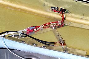
2. There is very little cross polarization. As proof, note the uniformly bad reports of using an Archer as a com antenna (which needs vertical polarization), unless the antenna can be tipped off the horizontal plane. And since both Loc and GS signals are horizontally polarized, using one antenna vs two does not help reject vertically polarized noise. One thing that is true, that you didn't mention, is that the gamma match is not optimally positioned for the GS, operating at triple the frequency. But,...

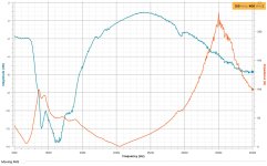
The bottom line is that modern receivers are so sensitive, that the signal strength doesn't matter much. What maters is the signal to noise ratio. If having an inefficient antenna lowers the signal, but also lowers the external noise, it's all good - until the signal gets so weak that internal noise (generated by the 'front end' of the receiver's electronics) starts to mask the signal. The internal noise figures for modern receivers are so low that this means a truly horrible antenna.

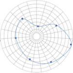
3. This is essentially correct. If the antenna sensitivity falls off so badly at 30 deg to the nose that the signal gets lost in the noise, you'll have a problem on intercept. But ILS's are all made to the same specs, and, as proven by quite a few Archer users, the antenna works fine at 30 deg off the nose for standard ILS signals. Now, maybe there's an ILS in Tim-buck-too that requires an intercept 50 nm out, I don't know about that. But the antenna even works at 90 deg off the nose, "looking" thru the fuselage, for somewhat distant VOR signals.

4. I have never seen a single NTSB report that blamed an accident on an inadequate ILS signal during the intercept. Lots of other problems, for sure, but not that.
 
Hi Andy, after you digest all the above info, I actually just bought a new archer type antenna that I'm now not going to use - wandering around the vendor booths at Sun-n-Fun changed my plans for my NAV gear ;) I paid $80 + shipping (they're $130+ at Aircraft Spruce) and will sell it for what I paid if you decide you'd like it.
 
Bob,
I am trying to keep it simple but your understanding of the way the ILS works is either not correct or I am missing something. So lets get to the engineering level for an in depth discussion.
ILS starts by mixing two modulating signals to the carrier, one at 90 Hz and another at 150Hz. This creates a signal with five radio frequencies in total, the carrier and four sidebands. This combined signal, known as the CSB for "carrier and sidebands", is sent out evenly from an antenna array ( the linear broadside array). The CSB is also sent into a circuit that suppresses the original carrier, leaving only the four sideband signals. This signal, known as SBO for "sidebands only", is also sent to the antenna array. I can show you the math if are not sure about this. The important point is the signal strength of the received signal on either side of the beam and across the beam is the same - essentially the same signal/noise ratio with modulation differences.

Each individual antenna in the array has a phase shifter that is applied only to the SBO such that the signal is retarded 90 degrees on the left side of the runway and advanced 90 on the right. Additionally, the 150 Hz signal is inverted on one side of the pattern, another 180 degree shift. Due to the way the signals mix in space, the SBO signals destructively interfere and eliminate each other along the centerline, leaving just the CSB. At any other location, on either side of the centerline, the SBO will not completely cancel out.

A receiver in front of the array will receive both of these signals mixed together. Using simple electronic filters, the original carrier and two sidebands can be separated and demodulated to extract the original amplitude modulated 90 and 150 Hz signals. These are then averaged to produce two (DC) signals. Each of these signals represents not the strength of the original signal, but the strength of the modulation relative to the carrier, which varies across the broadcast pattern. This has the great advantage that the measurement of angle is independent of range.

The two DC signals are then sent to a conventional voltmeter or encoded onto a data bus with the 90 Hz output pulling the needle right and the other left. Along the centreline the two sidebands will be cancelled out and both voltages will be zero, leaving the needle centered in the display. If the aircraft is far to the left, the 90 Hz signal will produce a strong DC voltage and the 150 Hz signal none at all, pulling the needle all the way to the right. As the measurement compares different parts of a single signal entirely in electronics, it provides angular resolution of less than a degree, and allows the construction of a precision approach.
The issue of suppression of cross polarized signal ( in this case vertical polarization) is all about providing maximum immunity to interfering signal within the band. I am sure you know that vertically polarized interfering transmissions will have more range than horizontally polarized transmissions and there are likely to be more sources of interference that are vertically polarized.
Bob, I am more than happy to have a technical discussion on avionics systems, transmission , propagation, electronics, navigation and control system - we can all learn something from the discussion. If expressing a personal opinion on the limitations of a practical and inexpensive gammi matched antenna for a VOR/ILS application jingles your bell I am sorry - it certainly wasn’t the intention.

KT
 
Bottom Line

From what people tell me, the Archer antenna works well. So i have installed one. In my test with the gNc255 vor/radio, it worked better than my spam can cessna trainer. I was in a close hangar, 100 yds off the centerline about mid field and still recieving ILS signals.
 
The airport localizer transmits in the VHF band with a signal modulated with two low frequencies. The relative phase between the two modulation frequencies being linearly dependent on angular position to the extended centerline of the runway and the beam.

KT

Hi Keith,
I think your description of the loc antenna is correct. I was confused by the quoted line above. I thought you meant ‘the relative phase between the two low modulation frequencies (90 and 150 Hz)…’ which made no sense to me. I see now you meant ‘the relative phase between the two RF signals (which are modulated differently)’.
This all reminds me of the argument over hidden GPS antennas, where I am generally against them while in favor of hidden Archer antennas for ILS. The difference is that GPS signals, and noise and interference levels, can vary all over the place, so testing in ‘poor conditions’ is hard to verify. ILS signals, otoh, are very standardized, so relatively straight forward in flight testing should be adequate.
 
You mean there are still pilots shooting ILS approaches?? :D
Yes almost every day. Every airliner you see landing at any major airport is doing an ILS even in VFR conditions. GPS approaches still have higher mins. However agree small airports often only have GPS approaches now. ILS will be around for many more decades, at least for commercial operators. What happens when the SATS are attacked by God who knows? Terrestrial local NAV aids will still rule.

Hi Everyone,
I just bought a beautiful flying 7A and I'm looking for the best solution to add a VOR/LOC/GS antenna. "best" means primarily best functioning, but also decent looking and reasonable cost. Has anyone installed the "do it yourself" kind in the wingtip AFTER the ship has been built? Do they work?
Any other solutions except the Aircraft Spruce black hockey puck looking one?
Andy.
To the OP. I am not a fan of the Archer antenna burried in one wing tip. When people say it works that is non qualified. If they say 100 miles, an external antenna might do 150 or 200 miles. They will retort they fly with buddies with VOR antenna outside and their plane has better reception range. Of course that is non qualified. I gave doubts about a wing tip antenna doing better than a properly installed external antenna with structure not blocking it. It is not "Rocket Surgery or Brain Engineering" (joke) to figure out your reception pattern will be greatly affected with antenna buried in the wink tip. I put my whisker on the belly of fuselage all the way back partly under under Horz Stab. You can get VOR/LOC/GS off of one VOR antenna. VOR/LOC are in same Freq range so that is good. GS is much higher but a splitter can take VOR antenna and split off GS as well.

https://www.rv7blog.com/2009/11/01/vor-antenna/
https://sarasotaavionics.com/avionics/ci-507

OR Antenna with splitter integrated
https://www.aircraftspruce.com/catalog/avpages/comantci158c.php

If speed is your thing here is a pre made fairing for belly moiunt.
https://www.rvplasticparts.com/product-page/fairing-comant-vor-loc-gs-antenna-ci-157p


On RV-7A's you can put the VOR dipole (whiskers) at top of Horz stab, but not recommended for tail dragger as it is at eye height and a hazard. On the belly it works for either trike or TW plane.

Top of Horz Stab mount of VOR/LOC/GS antenna on Trikes like an RV-7A.
http://www.aviatorshop.eu/RV-10/2017/12/08/vor-antenna-installation/


What is the point of putting antennas out in the wing tip (for arguably reduced performance)? You have the Con of associated hassle of wiring it through the wing for what SPEED? Sure that is going to make micro knot difference. The hidden or buried antenna idea was and is best for all composite planes. RV's are metal planes as God intended planes to be made. Ha ha. You can buy a VOR antenna used for $50, get a $200 splitter, good RG400 coaxial, mount it in belly in back or top of Horz stab. The routing of wires through the fuselage is far easier than wing. You will be blessed with better NAV performance. I guarantee it.
 
Last edited:
George,

The VOR/LOC/GS antenna goes in the wingtip because any option on the skin with both not needed, and ugly. And all those bolting it on the skin need to be very careful of how the high current part of the antenna (the part near the center) is coupled to the skin. Does anyone put an antenna analyzer on the final install to verify? I do. If you do this, please put eyeball protection on it (and all antennas sticking out the bottom) as I know of one RV builder that lost an eye because he forgot about it when cleaning the belly.

The objective is to the antenna meet the mission, not to be the best as measured on an instrumented antenna range. Shoot fire, I can build an real ugly antenna to work much better than the grossly overpriced commercial ones, but why?

At 100+nm VOR range it the wingtip meets the third navigation backup mission for my airplane. The LOC/GS performance has been measured far beyond approach ranges.

“Best” anything is typically not the right choice for our airplanes. We want best choice for our mission.

Carl
 
Regardless of the Nav antenna selection, internal or external, I suggest recording an antenna reception polar plot.
This exercise will identify weak reception directions and can be accomplished by tuning in a distance VOR. Make a slow 360 degree turn holding the wings as level as possible and record the relative signal strength at 30 degree intervals. The plot may look like the example below.

This method also works well for the VHF Com by using a distance ATIS.
 

Attachments

  • Polar-Graph-Template-Blank-250x251.png
    Polar-Graph-Template-Blank-250x251.png
    19.5 KB · Views: 279
George,

The VOR/LOC/GS antenna goes in the wingtip because any option on the skin with both not needed, and ugly. And all those bolting it on the skin need to be very careful of how the high current part of the antenna (the part near the center) is coupled to the skin. Does anyone put an antenna analyzer on the final install to verify? I do. If you do this, please put eyeball protection on it (and all antennas sticking out the bottom) as I know of one RV builder that lost an eye because he forgot about it when cleaning the belly.

The objective is to the antenna meet the mission, not to be the best as measured on an instrumented antenna range. Shoot fire, I can build an real ugly antenna to work much better than the grossly overpriced commercial ones, but why?

At 100+nm VOR range it the wingtip meets the third navigation backup mission for my airplane. The LOC/GS performance has been measured far beyond approach ranges.

“Best” anything is typically not the right choice for our airplanes. We want best choice for our mission.

Carl

The proximity and connections to the “high current” part of the antenna is only important for high power transmitting antenna. Not an issue for receiving only antenna. VSWR and beam pattern across the band are of far more importance. Measuring VSWR of the installed antenna with associated matching network is straightforward with relatively cheap test equipment bought from a ham radio outlet. Measuring the radiation pattern typically takes a scale mode, scaled frequencies and an antenna range to get a good representation of the beam patterns. “Certified” aircraft have been subjected to this level of testing as part of the type certificate. In the experimental world we have to rely on the “similar too” approach and “suck it and see” style testing. Not saying it cant be done- just why make it more difficult by going with a completely untested and unknown equipment and configuration.
KT
 
The proximity and connections to the “high current” part of the antenna is only important for high power transmitting antenna. Not an issue for receiving only antenna.SNIP..

A receiving antenna has the exact same electrical properties of a transmitting antenna. For any half wave dipole (like you suggest), the first third or so of each element is the current part, the rest is the voltage part.

Example of this is why a bent comm antenna is still essential vertically polarized. The current part does most of the transmit and receiving, the rest brings it into resonance.

Carl
 
George,

The VOR/LOC/GS antenna goes in the wingtip because any option on the skin with both not needed, and ugly. And all those bolting it on the skin need to be very careful of how the high current part of the antenna (the part near the center) is coupled to the skin. Does anyone put an antenna analyzer on the final install to verify? I do. If you do this, please put eyeball protection on it (and all antennas sticking out the bottom) as I know of one RV builder that lost an eye because he forgot about it when cleaning the belly.

The objective is to the antenna meet the mission, not to be the best as measured on an instrumented antenna range. Shoot fire, I can build an real ugly antenna to work much better than the grossly overpriced commercial ones, but why?

At 100+nm VOR range it the wingtip meets the third navigation backup mission for my airplane. The LOC/GS performance has been measured far beyond approach ranges.

“Best” anything is typically not the right choice for our airplanes. We want best choice for our mission.

Carl
UGLY? Do you not see my thumbnail of my dog? Ha ha. All this NAV range is highly dependent on the VOR (high altitude, lower, terminal) and your altitude. My point being an antenna in the wing tip will have a NULL in certain directions. With GPS VOR is relegated as a back up. So may be this VOR antenna thing is moot. However ILS (LOC/GS) I like the antenna outside and ugly. Ha ha.
 
Last edited:
Question for this thread

The group of folks here are way way beyond me in this avionics game. (I pretty much just put the wires together.)
But I need a little help in this area. My KX-125 has always worked fine in my old second-hand RV6 but lately it just quit receiving a signal. I am getting nothing - no nav signal at all. But I've found that when things break is when my learning curve goes up. I am trying to verify if my problem is the radio or the antenna. (I would have just pulled the radio and sent it off to the good people at Bevan but their very nice, extremely knowledgeable King expert has sadly passed away.) I figured out that I have a home-made antenna in my right wingtip (which is rivited on.). I finally found a location in the antenna coax with a connector. (I absolutely cannot access the back of the tray unless I remove several things.)
I have an old dipole cat whiskers antenna but in the looking I've done I see that it needs a Balun loop which I guess I can fab up. But if I just connect this dipole to the coax shield and center conductor will it work at all? Just trying to see if the radio will pickup any VOR signal.
Any help appreciated.

If you’re close enough to the transmitter a coat hangar will work. Yes, this should be adequate without the balun. If there’s a close by airport with an ILS, just park there in sight of the runway and try to get the localizer.
 
Archer Plot

I did a plot of the archer model 1 wingtip antenna. It shows how well this antenna is tuned: exactly 50 Ohms and max resonance (-13.5 dB) in the range 108 - 118 MHz.
It has no particular resonance at 330 MHz for the glide slope. The plot is 10 dB higher there.
This is measured with a 50 Ohm coax cable attached to the antenna per the installation instructions. A ground plane is overlapping 50% of the ground side of the antenna as per the instructions.
 

Attachments

  • archer_plot1.jpeg
    archer_plot1.jpeg
    180.1 KB · Views: 84
Last edited:
Back
Top