What's new
Van's Air Force

Don't miss anything! Register now for full access to the definitive RV support community.

Scott's RV-14A Panel Plan as of 4-7-21

rockitdoc

Well Known Member
Sponsor
Scott's RV-14A

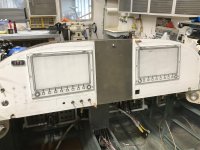
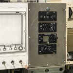
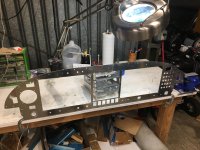
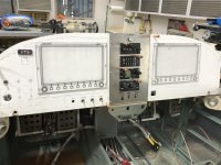
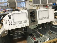
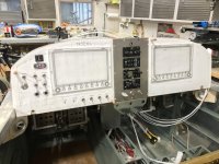
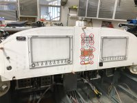
So, I 'think' I have decided to simplify the switches instead of ganging multiple functions into single switches. Originally, I was thinking fewer switches would be better on the front, but now, I think I would prefer individual switches for specific functions.

This means taking up more space on the front, but there is room to do it. So, I think it will make it easier for me to remember what each switch does. Also, it makes the rear a bit simpler since wires to switches are also for specific tasks.

The logic, so far, is that start up operations are clustered on the far left, when my left hand is not occupied with the stick. Lights, fuel pump and flaps are on the right above throttle, mixture and prop when my left is busy with the stick.

Anyway, take a look and give me your thoughts on how manageable you think this is. I appreciate your opinions since most of you have WAY more experience than I do.
 

Attachments

  • PAnel Mockup Switches 4-7-21.jpg
    PAnel Mockup Switches 4-7-21.jpg
    283.8 KB · Views: 402
Last edited:
Scott, I like to have a flow to the starting and to the shutdown. I prefer going left to right for the start-up, and right to left for the shutdown. Yours is more of a hopscotch pattern.

Now that's my preference, and I'm carrying it over from my Cessna 180 to my RV-3B project because it works so well.

You've got an avionics switch, but I think - check it - with Dynon you can leave the system on during start. That would give you engine data then. So your flow is:

Master,
Both mags,
Maybe the fuel pump to the right,
Back to the alternator,
Avionics,
etc.

A lot of jumping around.

Dave
 
In my panel, I opted for all single function switches - I have found I really like a quick glance that “everything is down” after shutdown. The most significant duplication is landing lights and wig-wag as 2 switches where they are often on a 3-way - but I like them separate.

I also grouped left switches for startup (flow) except fuel boost which I put on the right near the flap and throttle. Hopscotch? - maybe but a tradeoff I prefer.

I opted to include an avionics switch (relay based). My reasoning was for easy load shedding in an emergency, but it has also proved beneficial for the frequent boot ups in the shop (even just to get Hobbs hours) that don’t fire up the entire panel.

The bottom line is that you quickly learn your plane and your panel. The fine points would only be an issue for the occasional pilot used to different layouts. IMO and YMMV.
 
First Iteration

So, my first try at this panel looks like this based on a starting sequence of, from top-down and left to right (except fuel pump and USB):

0. ELT On
1. Master On
2. Alternator On
3. Avionics On
3a. Load flight plan(s) via USB if this is necessary
4. Left PMag On
5. Right PMag On
6. Fuel Pump On, until peak flow, Off
7. Start Button until starts
8. Throttle to 1000 rpm, oil pressure check
etc, etc including radio, lights, etc.

If this sequence seems problematic for any reason, please chime in. I appreciate the help and your expertise always.
 

Attachments

  • Panel Layout.jpg
    Panel Layout.jpg
    350.7 KB · Views: 306
What does the avionics switch do for you? Can you eliminate it?

Is your ELT on battery power if it's switch is on and the master is off? Because some are not, and those switches can be left on.

I like to have the prop and mixture set for starting before I turn on the electrical stuff. That way I'm not burning amps or gasoline while I adjust them.

Dave
 
Scott, I would swap the knob module and the AP control. You will use the knob module far more and it sure is nice in turbulence being able to brace your hand on the top skin/panel.

I would also move that stack up as high as possible.

Looking good.
 
The ELT "on" function on the ACK panel there activates the ELT in case it doesn't activate on it's own in a crash, you definitely don't want to turn it on before flight. The ELT is battery powered so you don't need to do anything on that panel except for using the "test" function normally so I would move that ACK panel lower and perhaps put a standby attitude indicator there in your normal scan area.
 
What does the avionics switch do for you? Can you eliminate it?

Is your ELT on battery power if it's switch is on and the master is off? Because some are not, and those switches can be left on.

I like to have the prop and mixture set for starting before I turn on the electrical stuff. That way I'm not burning amps or gasoline while I adjust them.

Dave

Actually, the avionics could come on with the Master, I suppose. No need to be separate, unless one wanted to be able to switch them off in flight, without turning off Master. In case of smoke coming out of the EFIS, etc?

I think my ELT has it's own battery. Not sure, though. IT's going to be the ACK.
 
Scott, I would swap the knob module and the AP control. You will use the knob module far more and it sure is nice in turbulence being able to brace your hand on the top skin/panel.

I would also move that stack up as high as possible.

Looking good.

Good advice. Thanks.
I am planning to move everything up about another 1". I am thinking the closer the EFIS's are to the glare shield, the more shade and maybe better visibility?

Another thing: Do you think it would be worthwhile to angle the right EFIS slightly toward the pilot for easier reading? Maybe turn it so the left side is 1" forward of the the panel front and the right side its 1" aft of the panel front?
 
If you are going to cut you panel by hand like many people, these screw holes are PIA to mount the mini nutplates, especially when you have them so close together as in your panel layout. I space mine out by 1/4 inch. I mounted mine in the vertical orientation but that is just personal preference. The hole slot for the intercom is not the same as the autopilot and the radio.
 

Attachments

  • Panel Layout.jpg
    Panel Layout.jpg
    665.6 KB · Views: 277
Good advice. Thanks.
I am planning to move everything up about another 1". I am thinking the closer the EFIS's are to the glare shield, the more shade and maybe better visibility?

Another thing: Do you think it would be worthwhile to angle the right EFIS slightly toward the pilot for easier reading? Maybe turn it so the left side is 1" forward of the the panel front and the right side its 1" aft of the panel front?

I have never really noticed any limited visibility of the screens even with bright sunlight. Moving them up would still be advantageous though so you don't have to avert your eyes so far from their main job of traffic scanning.

While angling the screen on the right wouldn't be a bad idea I don't think I would go through the effort of doing it. IDK if you have seen one of these screens in person yet but they are pretty dang easy to see in almost all light conditions and angles. I am very impressed with mine so far!
I have not seen one in person in the sun. It would be a fabrication challenge to angle the right screen. Maybe i should plan a trip north to see yours!
 
I have not seen one in person in the sun. It would be a fabrication challenge to angle the right screen. Maybe i should plan a trip north to see yours!

Oh snap, I just realized where you are! Anytime come on up!

Once I'm out of phase 1 I may find myself down there a bit too. :D I got family that lives up by the Red Feather lakes.
 
Oh snap, I just realized where you are! Anytime come on up!

Once I'm out of phase 1 I may find myself down there a bit too. :D I got family that lives up by the Red Feather lakes.

PM sentttttttttt. 10 character min.
 
Repositioned Canopy Jettison Handle

I wanted my canopy jettison handle in the center of the panel, behind the panel, or under it. I realize using the thing in flight has 0 probability of occurring and using it after crashing and being upside down wouldn't help me get out with the canopy on the ground, but it would be handy for maintenance of the avionics, and the off chance that I'm right side up after a crash and the bird is on fire and the port side latch is broken. Anyway, after wondering if the handle should be pinned to prevent inadvertent activation by a curious passenger, and figuring this would be possible but maybe not too elegant, and sleeping on it for two nights, I finally came up with 'my' solution.

I welded up a handle not unlike the one that comes with the Finish Kit for the -14A. Except mine is oriented to the center of the panel. Since this makes the rod come out of the panel at an angle (not elegant) the rod has to be bent in two directions. No biggie. The handle is a highly customized carriage bolt from the aircraft section of Ace Hardware. When in position at the highest elevation I could get it on my panel, the carriage bolt....I mean centered forward canopy activation handle....is close enough to the panel that activating it has to be fairly deliberate. So, accidental pulling by a passenger is essentially nullified. Also, the distance it has to be pulled aft to release the canopy is about 6 inches. So, I'm confident the canopy won't get jettisoned by accident. :D

So, onward to the next trick, custom modifiication right after I powder coat the Centered Forward Canopy Activation Handle.
 

Attachments

  • Panel Center Jettison Knob.jpg
    Panel Center Jettison Knob.jpg
    340.2 KB · Views: 221
  • Panel Center Jett Knob Closeup.jpg
    Panel Center Jett Knob Closeup.jpg
    241.5 KB · Views: 221
  • Panel Center Jett Knob Pulled.jpg
    Panel Center Jett Knob Pulled.jpg
    279.6 KB · Views: 237
  • Panel Center Knob and Knob Panel Template.jpg
    Panel Center Knob and Knob Panel Template.jpg
    247.8 KB · Views: 207
I Get to Make Center Panel AGAIN Tomorrow!

So, after meticulous measuring, cutting, and filing today to get my center panel instruments installed, I found out the Dynon template for the Intercom is too large. The template indicates the hole should be 1.24" x 3.36". But, the intercom is only 1" x 3". So, since I used the template to plan my cuts (dumb me) the spacing for the intercom is different than my other three pieces. Ugh.:mad:
Oh well, I now have 8 hrs practice making the center panel, so v 2.0 should be right on.

I told Dynon.
 

Attachments

  • Panel Center with Radios, etc v1.0.jpg
    Panel Center with Radios, etc v1.0.jpg
    335.3 KB · Views: 259
Sorry to hear that Scott! I didn't use the template but measured very accurately with the drawing they provide. It sure took awhile but it worked. I do remember there not being much room for any oversize on the holes; very low margin indeed.
 
Just finished

I just finished cutting my panel holes tonight. Dont feel bad about redoing a panel. I just got done drilling the switch holes, then filing them square for my 9 switches. Now I found out a friend has a square panel punch. Duh! But I guess it builds character turning round holes into square holes by hand.
 

Attachments

  • DB3ED766-FAFA-40CA-A288-37C595B6969A.jpg
    DB3ED766-FAFA-40CA-A288-37C595B6969A.jpg
    381 KB · Views: 249
Last edited:
v 2.0 of Center Panel

I redid the center panel today. 4 hours, this time. The 8 hours spent yesterday on v 1.0 helped.


Still trying to decide if I need that A/P switch at the bottom of the center panel. Don't I have an on-off switch right above on the A/P controller?

Also, I think I want the flap switch right above the throttle, but symmetry keeps telling me to put it in the center.

I also moved the USB's to the left side below the ELT. I figure I will be loading flight plans from the home computer/iPad, so this is one of the first things I will do on sitting down. Haven't made up my mind on this, though.

What say you sage builders/fliers?
 

Attachments

  • Panel Center with Instruments Centered.jpg
    Panel Center with Instruments Centered.jpg
    332.4 KB · Views: 308
Last edited:
I redid the center panel today. 4 hours, this time. The 8 hours spent yesterday on v 1.0 helped.


Still trying to decide if I need that A/P switch at the bottom of the center panel. Don't I have an on-off switch right above on the A/P controller?

Also, I think I want the flap switch right above the throttle, but symmetry keeps telling me to put it in the center.

I also moved the USB's to the left side below the ELT. I figure I will be loading flight plans from the home computer/iPad, so this is one of the first things I will do on sitting down. Haven't made up my mind on this, though.

What say you sage builders/fliers?

What A/P switch are you referring to? I have one that can turn the power to the motors off just in case but I never use it. Glad to know it's there though. The AP control can turn it off, the screen itself can turn it off, and if you put a disconnect on the grip it can turn it off. I suspect I'll never have to use the switch on the panel.

Definitely recommend your flap switch above the throttle, I did that on mine and I don't ever have to take my hand off the throttle when approaching.

Do you have a boost pump switch? That is the other heavily used one.

Good move on the USB. I put mine on the right side and it is annoying to have to stretch to put the USB in. I didn't realize how much I would use it. I use it every flight to pull data.
 
'Latest' Version of Panel

OK, chime in. Before I cut more 6061, what is missing? This is a class project remember?:D

I prolly will swap the USB ports and the ELT for symmetry.

Should I install a Hobbs?
 

Attachments

  • Panel Mockup with Center v2.1.jpg
    Panel Mockup with Center v2.1.jpg
    408.1 KB · Views: 278
Last edited:
Panel as of 4-19-21

I mounted all the stack instruments. Sixteen nut plates in close proximity to the cuts makes for slow going. But, all done, and the machine screws even lined up after all the riveting!

I installed the switches; flaps, fuel boost, A/P under the stack.

And, I switched the position of the ELT and USB. The USB on the panel will only be used to download flight plans and update software. I'll just put a USB in the 12v outlet between the seats for charging phones and other things not flight related.

Two more Honeywell SPST switches coming for the panel and cabin lights (Thanks Jason E for reminding me about those)

Started plugging in harnesses and trying to figure out where all the wires will go. This is going to take some time. There is a LOT of potential for tangled spaghetti behind the panel!
 

Attachments

  • Panel Mockup 4-19-21.jpg
    Panel Mockup 4-19-21.jpg
    337.1 KB · Views: 303
I mounted all the stack instruments. Sixteen nut plates in close proximity to the cuts makes for slow going. But, all done, and the machine screws even lined up after all the riveting!

I installed the switches; flaps, fuel boost, A/P under the stack.

And, I switched the position of the ELT and USB. The USB on the panel will only be used to download flight plans and update software. I'll just put a USB in the 12v outlet between the seats for charging phones and other things not flight related.

Two more Honeywell SPST switches coming for the panel and cabin lights (Thanks Jason E for reminding me about those)

Started plugging in harnesses and trying to figure out where all the wires will go. This is going to take some time. There is a LOT of potential for tangled spaghetti behind the panel!

I hate to say it but....IMHO if you use the USB plug-in while flying, the cord will be draping across all the switches below and be very annoying.
 
I hate to say it but....IMHO if you use the USB plug-in while flying, the cord will be draping across all the switches below and be very annoying.

This is a good point.

Just to clarify Scott. The moving of the USB for the EFIS to left side was a good move. I do not charge anything out of this port but routinely put a USB drive in it every flight for data pulls, uploads, and screenshots. In fact I even laser engraved the cover to say "EFIS DATA ONLY". However, I also have another USB port in my plane totally dedicated to charging devices on the right side. This could be a good addition to your panel as well. Hope this helps!
 
I hate to say it but....IMHO if you use the USB plug-in while flying, the cord will be draping across all the switches below and be very annoying.

I agree. That is why the USB on the panel will not be used for anything with a cord. It's just for a data stick to load data to EFIS or for wifi.

I will plug a USB port into the +12v socket between the seats for corded thingies.
 
This is a good point.

Just to clarify Scott. The moving of the USB for the EFIS to left side was a good move. I do not charge anything out of this port but routinely put a USB drive in it every flight for data pulls, uploads, and screenshots. In fact I even laser engraved the cover to say "EFIS DATA ONLY". However, I also have another USB port in my plane totally dedicated to charging devices on the right side. This could be a good addition to your panel as well. Hope this helps!

Agree. I like the label idea, too.

Will a USB adapter plugged into the +12v outlet between the seats work for charging iphones and such?
 
Agree. I like the label idea, too.

Will a USB adapter plugged into the +12v outlet between the seats work for charging iphones and such?

I guess I am unfamiliar with how the 14 plans are on this area but I just have a separate usb plug on the panel that just gets a 12v pwr and ground wire so it sounds like the same.
 
I guess I am unfamiliar with how the 14 plans are on this area but I just have a separate usb plug on the panel that just gets a 12v pwr and ground wire so it sounds like the same.

I just realized the -14 comes with both a +12v power outlet and a dual USB outlet (marked 4.8mA from Blue Sea) intended for a spot between the seats along with an audio output plug! I should have done a better job inventorying my FWF stuff. Not sure why something in the cabin comes with the FWF kit. Oh, well. Nice. Problem solved, and no need for a USB adapter plugged into the +12v port.
 

Attachments

  • POwer and USB Plugs.jpg
    POwer and USB Plugs.jpg
    301.9 KB · Views: 340
Back
Top