What's new
Van's Air Force

Don't miss anything! Register now for full access to the definitive RV support community.

RV-9A, pilotjohns

Canopy, Part 2 - The Big Cut

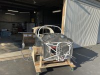
Today was a warm day, perfect for canopy work.

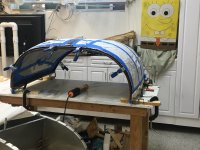
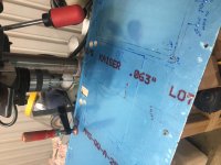
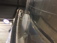
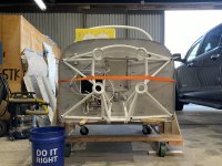
This weekend was all about cutting the canopy down to size. The on-line experts suggested to use the Dremel Max Saw. This worked out very well. However, they recommended the SM500 plastic blade, I found this to be a really coarse cut. I chose to use the SM510 metal blade. This blade is just like the cut off wheel Van's supplies in the kit, but for the Max Saw. With this blade, if the cuts are made carefully, there is very little clean up sanding. I took everything down to 240 grit after the cut, before moving the canopy.

The cutting wasn't as bad as others have made it out to be.It is only a (very expensive) piece of plastic. It isn't like it is a Ferrari or anything. Like everything else on this build, I was stressing over it and it turned out to be not worthy. With all the others writing of their experience, that background helped a lot. (Thank you)

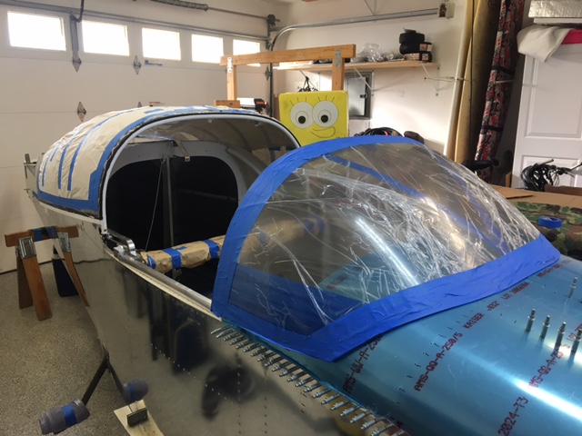
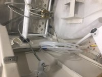
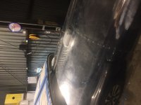
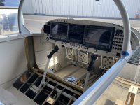
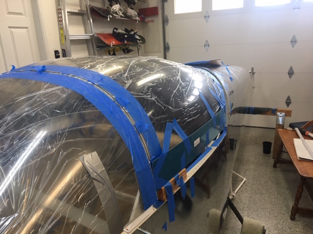
I taped the canopy to the frame for a fit check using wire as a Sika spacer. Seems I have a few more trim cuts to make, so I figure another whole day in the sun and then it will be ready to bond.

I am thinking of not using the trim piece that sits on the outside, down the middle spine. It seems with the Sika bonding method, there is no need for this strip. But
I think I will need to bond on a thrust washer for the handle thou.

IMG_2136.JPG
 
Canopy Part 3 Gluing

Got the canopy glued to the frame today. Used the sikaflex method as outlined by VAF’s Wirejock in an earlier post.

Like everything else the fear was worse than the event. Yes it was a mess, I think I got some of the black stuff in my hair because I have a grey spot that disappeared after I was done gluing.

I used tbe 3m fine line painters tape. This worked out well. I tried to add a layer of electrical tape on top like Wirejock recommended, but this wouldn’t stick. After prime I pulled off the 3m tape and then Re-taped with electrical tape to make it easier to make a fillet. This didnt work. It would have been better to just pull the 3m tape after prime and leave the primer’s edge untapped.

I set the frame upright, added a bead of sikaflex to the frame’s Spine, front and rear bows with the spacers, then dropped the canopy on top. After it was position and clamped, I added the side plywood to shape the sides and then added a bead between the side bows and canopy. I did not use the side canopy supports.

The canopy is clamped to the table so it wouldnt fall off The bench if bumped. Now I get to wait 48 hours in bliss thinking I did an excellent job. I am sure reality will set in after a few days when I unclamp and get a good look at the bonds.
 

Attachments

  • 39FD5E0D-5C3A-4ACC-9CAF-D0B9B69BD242.jpg
    39FD5E0D-5C3A-4ACC-9CAF-D0B9B69BD242.jpg
    330.6 KB · Views: 1,202
Last edited:
Canopy Success

I finished up gluing the canopy to the frame and it came out well, I am very happy with the Sikaflex method and thinks it is the only way to go.

The canopy and canopy rails have been installed, along with the rear anchor blocks, and Supertracks.

I used the anchor block drill guide from RVPlasticParts.com and the angles were spot on. I had to shim one side in the tool to get the hole in the correct left and right location; this was mainly due to the fact that I had to move the anchor blocks outboard slightly to make sure there was the proper edge distance for the screw hole in the longeron.

I did a preliminary trim of the windscreen and marked the forward edge of the windscreen on the top forward fuselage skin. This will allow be to mask off and paint the portion of the skin inside the windscreen dark grey before final riveting.

I plan to finish the windscreen final trimming and canopy's fiberglass work once I am done with the instruments, electrical and engine forward installation. I want to build up my fiberglass skills on the tail feathers and cowling before tackling the canopy. (pun intended)

I am now starting on the final forward fuselage stuff working from the floor up, and firewall forward. I hope to be done Tuesday. ;-)

IMG_2213.JPG
 
I'm right behind you

John,
I'm finishing the bending of the canopy frame to the fuselage (my latest pic is on the VAF front page now). I have to get the gap between the roll bar and the canopy frame a bit closer and my fuselage sides are flush versus 1/16" inset but think that's ok... Question what is your canopy bonded to along the horizontal line were the skirt mounts? Thanks for any comments.
 
Oh the great debate

John,
I'm finishing the bending of the canopy frame to the fuselage (my latest pic is on the VAF front page now). I have to get the gap between the roll bar and the canopy frame a bit closer and my fuselage sides are flush versus 1/16" inset but think that's ok... Question what is your canopy bonded to along the horizontal line were the skirt mounts? Thanks for any comments.

Oh the great debate.
Some have used the traditional metal piece on the inside that sandwiches the canopy. I did not do this. Mainly because this area needs 1/8" gap for the Sikaflex to, well, flex. This would have pushed the canopy out too far on the sides and caused a poor fit for the side skirts.
Instead, I cut the canopy up about a 1/4" above the side rail, and then just used a extra wide bead of Sikaflex. before bonding, I covered the side skirts with clear packaging tape and this formed a mold for the Sikaflex fillet in this gap area, and allowed me to clamp the canopy in position while the Sikaflex cured. Since I had this gap, I let the Sikaflex cure for the full 7 days before disturbing it. With this method, the canopy touches the front and rear hoops where the side rails are welded. This is the only place the Sikaflex does not have the recommended 1/8" gap.

By the way, your frame fit looks awesome; I am glad you didn't throw down this challenge before I bonded my canopy on; if you had, I would still be tweaking my frame.
 
Last edited:
Wiring, or making rats' nests

So I started finishing the wiring. My goal is to get all the wires in the fuselage before installing the engine and instruments. This will keep me from having to bend over and under the panel to install the wires and fuel lines on the fuselage floor. The wiring from the spar back was all done a month ago, but the wiring on the floor, in front of the spar, took some doing. This involved planning out all the wiring runs and finding enough holes in the spar to bring the wires through. It also meant I had to install the transponder and comm antennas to get those cables routed. I had to use a cat5e computer cable to get all the stick grip signals to the instrument panel; running individual wires for all the functions on the grips would have never fit through the existing spar holes. The cat5e cable used 4 pairs of 28 AWG wires in a very tight bundle, giving me 8 functions spread between the two stick grips. (I think my wife doesn't need an intercom button, at least that is what I will tell her, sorry dear, no intercom button for you. For you none pilots, the intercom doesn't need a button, simply speaking makes the intercom transmit one's voice to all others, but the joke is I won't tell her that)

I also put in the parking brake and made a bracket for the parking brake cable and the micro switch to tell me the parking brake is on.

Next up is the fuel system final install on the fuse floor. This has already been installed, but now it is time for final install.

In my spare time, I have been creating the panel wiring schematic. It seems I need 6 each RS232 outputs but only have 5 available. The G3X experts from Garmin helped me out and said if I run an independent GPS antenna for the G5, then I don't need a 6th RS232 output. I think that is what I will do; this will make the G5 a true system backup, able to get me to VFR weather if everything else goes COVID on me.

IMG_2347.JPG


Edit: OK trick question: which wire did I forget? It is obvious and was expected since the wire looms are so nice.

9/2021 update: several lessons learnt. Dont use cat 5e or cat 7e wire, use proper aircraft wire. During first turn on, got an error message that pilot PTT (mikekey) is stuck on. Apparently cat wire had a low resistance short from being tied into the bundle. The wire is too flimsy. Also eight 22awg wires are about the same diameter, so cat wire didnt save much. Also added trim to copilot stick. Otherwise there would have been no redundant trim if the pilot’s stick trim buttons broke in flight.
 
Last edited:
Firewall and Engine Prep

Great progress these past few months. It seems as one gets closer to being done, many more decision need to be made by oneself. The plans become "a guide" and not instructions carved in stone.

For the engine, it seems there are two oil configuration choices for fixed pitch prop. The difference for a fixed pitch is the oil that normal goes to the prop needs to go somewhere and not build up pressure in the forward part of the crank. There seems to be two ways to do this when using fixed pitch. First is to use the normal oil return to the governor by letting the oil return through the governor cover that has a milled slot. This is shown in the picture of my cover plate. The second way is to open up the front crank plug, punch a hole in the rear crank plug, and then reinstall the front crank plug. Then one could remove the governor line from the front to the back and plug the fitting holes in the case. Since I had the governor line in place and the front crankshaft plug already factory installed, I just verified the rear governor cover had the milled slot and than put everything back together as shipped from factory. This way a future conversion to a constant speed prop will be easy. I also installed the alternator on the vac pump pad and checked the torque on the fittings that were factory installed. I still need to put the oil and fuel fittings onto the accessory case.

For the firewall, most of the electrical stuff that attaches to the firewall is installed. I still have to assembly the wires with lugs and stuff. Here is how I did the current shunt and the ANL fuses. I have everything with 12V power on fusible links or ANL fuses before passing thru the firewall. I am using a single shunt set up to read battery charge and discharge current. This will tell me if the alternator is putting out sufficient current to charge the battery or if my load is too great and discharging the battery. Please note the copper bus bars are not straight. This was done to allow some expansion and contraction so as not to pull or push on the contactor terminals. Moving forward (Pun Intended)
 

Attachments

  • IMG_2460.JPG
    IMG_2460.JPG
    115.1 KB · Views: 401
  • IMG_2475.JPG
    IMG_2475.JPG
    98.2 KB · Views: 481
  • IMG_2479.JPG
    IMG_2479.JPG
    108.7 KB · Views: 428
  • IMG_2480.JPG
    IMG_2480.JPG
    126.1 KB · Views: 473
Last edited:
Center Stack Wiring

Just a quick update.
Center radio stack wiring nearly done. About 100 terminations so far. Only another 150 or so to go.

If you look closely at the picture, lots of things going on. For example, supports modified to allow screens to be high on panel. Connectors are mounted on brackets in approximate locations to allow nice harness routing. Harness pass thru holes in sub panel. Fuse block installed. Wires labeled with printed heatshrink. Splices and terminations are inside backshells for greater reliability and better EMI (dont try this at home, it can go wrong if not carefully done)
 

Attachments

  • 0E2EB6A1-8DDF-4743-9C56-7226BC4CBBE7.jpg
    0E2EB6A1-8DDF-4743-9C56-7226BC4CBBE7.jpg
    389.3 KB · Views: 414
Last edited:
Great progress. The wiring is so different than everything else on the plane. Jut relaxing. Shield drain, cut, strip, crimp, heat shrink, then do it again hundreds of times!
 
Instrument panel

Just an update: after 3 months the subpanel wiring is almost done. I need to add the instrument panel to wire the subpanel and instrument panel together. Only 3 missed pins during subpanel wire check; not bad for 250 terminations.

Started cutting holes in panel for all the switches and stuff. Went old school with drill and file; seems to be acceptable if I dont get in a hurry.

Some days at the airport, it has been really slow. One day it was really really slow and I caught the blimp doing an approach and going missed. Cant imagine tower telling a following cessna 172 to slow down because he is overtaking traffic on final.
 

Attachments

  • 8CBA1B7A-3ECD-472C-8E93-DA6B7E020B24.jpg
    8CBA1B7A-3ECD-472C-8E93-DA6B7E020B24.jpg
    249.4 KB · Views: 380
  • 909A04C0-88F5-429C-9526-6EED6372A8A9.jpeg
    909A04C0-88F5-429C-9526-6EED6372A8A9.jpeg
    566.6 KB · Views: 429
  • 759590FC-3E30-4F96-A7AB-BA546F51C4A4.jpg
    759590FC-3E30-4F96-A7AB-BA546F51C4A4.jpg
    266.9 KB · Views: 404
Last edited:
Panel Cutting

Just a quick update.
Finish initial cutting of panel; going old school with drill, jigsaw and file. It came out well I think.
Next Up is to test fit everything, mount center rack supports, then prime, paint, mark and re assemble switches before final wiring. I figure I will be done on a Tuesday.
 

Attachments

  • B645D942-3638-44A8-AD28-26A62564741D.jpg
    B645D942-3638-44A8-AD28-26A62564741D.jpg
    381 KB · Views: 438
I just thought about the blimp doing touch and goes and had to chuckle. :D

Every so often there’s been a blimp at LVK doing exactly that. They use the field south of 25L, come in right over the south hangars, drag their tie down ropes on the grass. Also, overheard on LVK tower frequency:
LVK tower: Cessna 123, traffic, 9 o’clock, blimp.
Cessna 123: Uh, still looking, can you call traffic again?
LVK tower: It’s a BLIMP, for Pete’s sake. Just look out your window!
 
Wrong day

Just a quick update.
Finish initial cutting of panel; going old school with drill, jigsaw and file. It came out well I think.
Next Up is to test fit everything, mount center rack supports, then prime, paint, mark and re assemble switches before final wiring. I figure I will be done on a Tuesday.

When folks ask, I always respond immediately with "Saturday"
 
Just an update: after 3 months the subpanel wiring is almost done. I need to add the instrument panel to wire the subpanel and instrument panel together. Only 3 missed pins during subpanel wire check; not bad for 250 terminations.

Started cutting holes in panel for all the switches and stuff. Went old school with drill and file; seems to be acceptable if I dont get in a hurry.

Some days at the airport, it has been really slow. One day it was really really slow and I caught the blimp doing an approach and going missed. Cant imagine tower telling a following cessna 172 to slow down because he is overtaking traffic on final.


Maybe more of a "bounce" and go. ha

JD
 
While we are the subject

Just an updated firewall forward schematic.
 

Attachments

  • E7AC857B-86EF-4722-8158-DEB823A0700D.jpeg
    E7AC857B-86EF-4722-8158-DEB823A0700D.jpeg
    325.9 KB · Views: 443
Panel First Look

Panel painted and assembly started.
 

Attachments

  • 811EBB49-5852-4362-85DE-3764F7C4380D.jpg
    811EBB49-5852-4362-85DE-3764F7C4380D.jpg
    323.5 KB · Views: 446
Panel Updates

Panel is nearly done with the wiring. Many things I have learnt from all of this.

AP wiring: I had the AP power controlled by a switch and fused instead of a circuit breaker. The G3x manual shows the 507 controller and servos all being powered from the same fuse. I originally had the 507 and servos on a switch, but I have changed that to just the servos on a switch. That way, if I kill the servo power, the 507 stays powered and should give be pretty purple boxes as guidance; there seems to be no reason to kill power to the 507 in an emergency as long as the servos are powered off. The AP switch is wired so that the green portion is illuminated when AP is powered, and the red portion is illuminated when there is no power to the AP servos

Bus bars: i made the circuit breaker’s bus bars out of copper sheet. I wish I would have spaced the circuit breakers out more; it would have been easier to get the screws in. Also, the CB screws are flat heads, these should be changed to round head Allen or Philips style; it is hard to start the screws using a flat bladed screw driver. I found labeling the back of the CBs really helpful.

The bus bars have clear shrink tubing over the areas between contacts to minimize potential for shorts. This is all protected with an 35A ANL fuse forward of the firewall.

There is no longer a AP disconnect switch on the panel. I dont see a need to disconnect the autopilot unless my hand is on the stick, so only the stick has a disconnect (along with the "AP" button on the 507). The trim CB was moved in front of the pilot and position to be operated with the right hand. If I have a runaway trim, one hand is going to be fighting the stick, so I want to other to be able to pull the trim CB.

The defrost fans did not need both a switch and a CB, but I had extra CB holes and my fuses were all assigned. so room for growth.

I was hemming and hawing about the defrost fans. I was thinking of putting the antennas on the glare shield in recessed mounts. I gave up on that so the fans are staying on the glare shield. The antennas will go under the cowl.

I painted the panel with the Sherman Williams Jet Flex that I used on the interior of the fuse. This paint is really good; flows out easily, is durable, and just works.

The taxi lights and landing lights are on the same switch. I wanted a off-taxi on-landing light on switch, but the world wide shortage has me with a taxi on-off-landing light on. I will switch this out once the preferred switch becomes available.

The radio stack is not quite centered, I moved the left screen, the rack and the right screen as far over to the left as I could go. I was hoping the left screen was centered in front of pilot, but didn't quite get there with the G5's position.

Lastly, all power terminals screws have lock washers. (yes I changed my mind)
 

Attachments

  • 7F0BAE44-03FB-4B9C-AA6C-88D300E595AC.jpg
    7F0BAE44-03FB-4B9C-AA6C-88D300E595AC.jpg
    196.6 KB · Views: 463
  • B11F5D72-B171-498B-B789-661CA8943705.jpg
    B11F5D72-B171-498B-B789-661CA8943705.jpg
    399.2 KB · Views: 460
  • FB2690A0-3C73-478B-8083-AC641521E965.jpg
    FB2690A0-3C73-478B-8083-AC641521E965.jpg
    472.1 KB · Views: 442
Last edited:
PANAL

Nice job on the panel. Not many things rate up there with wiring your own panel and putting power to it!! Panel. Not panal!
 
Last edited:
Bench Wiring Calling Done

Well today I am calling done the bench wiring of the Panel and Sub-panel. I cant think of anything else I can do on the bench before installing it and hooking everything up to the stuff already wired in the plane.

Here are the pics on the bench of all the stuff. There is really a lot of boxes and wiring in this panel. It didn't look so bad when viewing the schematic several months ago.

I can't light it up without the antennas hooked up, so I will just pretend that is is wired correctly.

I have been neglecting the fuselage wiring; so now it is time to clean that up, and get all the fuselage foot well stuff done prior to putting in this panel structure.

In other news, coming up on 5 years. Really hope to be done this year. Hope it is all downhill from here (panel wiring done).
 

Attachments

  • image(1).jpg
    image(1).jpg
    143.6 KB · Views: 395
  • image(4).jpg
    image(4).jpg
    118.1 KB · Views: 402
  • image(5).jpg
    image(5).jpg
    124.5 KB · Views: 357
  • image(6).jpg
    image(6).jpg
    93.6 KB · Views: 312
  • image(7).jpg
    image(7).jpg
    143.5 KB · Views: 368
  • image(9).jpg
    image(9).jpg
    142.6 KB · Views: 371
  • image(8).jpg
    image(8).jpg
    164.4 KB · Views: 361
  • image(2).jpg
    image(2).jpg
    122.1 KB · Views: 354
  • image(3).jpg
    image(3).jpg
    130 KB · Views: 312
  • 75CC323B-ED05-44DE-92B7-07D0DDC2C9F1.jpeg
    75CC323B-ED05-44DE-92B7-07D0DDC2C9F1.jpeg
    721 KB · Views: 435
  • CFCDAA44-D84D-4F20-98FE-079BF9F630D2.jpg
    CFCDAA44-D84D-4F20-98FE-079BF9F630D2.jpg
    304 KB · Views: 375
Last edited:
Yes

It sure looks intimidating to an outsider.
I thought about that before posting, but the truth is the truth. It is just one wire at a time. Also, a simpler panel is way less wires.

But I wanted my plane to be like the big boys so I can push the autopilot button on rotation, take a snooze, wake up on short final, push a button to release control back to the pilot, and land.
 
I can't light it up without the antennas hooked up, so I will just pretend that is is wired correctly.

You can at least do the "smoke test" to ensure all your power lines go to power and data lines go to data. I lit up my panel right after wiring to make sure, with no antennas attached. Nothing popped or smoked, but I did find one RS-232 pair with Tx and Rx reversed.
 
Just me

You can at least do the "smoke test" to ensure all your power lines go to power and data lines go to data. I lit up my panel right after wiring to make sure, with no antennas attached. Nothing popped or smoked, but I did find one RS-232 pair with Tx and Rx reversed.

I was trying to figure out how to apply power on the bench and I realized there are so many interfaces not hooked up it seemed pointless. So for one last time I ohm checked all the power and ground wires. I thought I had a short when the power to ground measurement read 80 ohms. I started freaking out and then realized the taxi light relay was in circuit. Everything measured OK.

Next step is to finish all I can in the cockpit before installing the panel..
I am almost there…….
 
Final Fuse Push

Now that the panel is done enough to install, I have been working to finish all the fuselage stuff to limit the amount of work I need to do on my back once the panel is installed.

First off was to finish the fuel lines. I have been putting this off because I didn't want to keep hitting them as I walked around the airplane. Now it was time to install. My hat is off to those who did this per the plans; I was not able to get a single line from the valve to the wing roots, so I broke it up into three pieces. Ya the extra breaks have more potential for leaks, but I am using 200 PSI fittings for a maximum of 8 psi; so I think it will be OK.

Next up was figuring out the GPS and XM antenna placements. I was planning on putting them just forward of the firewall, exactly like what is NOT recommended due to heat. Then I thought about a place on the glare shield, but I didn't like seeing over them all the time. I thought the rear turtle deck would not work because I was afraid the canopy would not slide over them. Turns out someone posted a picture on these forums and guess what, the canopy clears them by a large margin. So I ended up installing the GPS antennas in the preferred locations on top the fuselage. Now I have to spend $200 on 50 feet of RG400 cable to run to the back. Oh well. Here are my antennas installed temporarily so that I can run the antenna wires. I think this is going to work out great!
I also installed the parking brake handle. I had to redo the idiot light switch. (I was an idiot the first time). I had it activate when the lever pushed on it, but a slight shaking would cause it to be intermittent. I changed it so that it is activated when the lever sweeps past it; no longer susceptible to vibrations.
I still need to torque everything, and then torque strip.
Next up is prep for the engine mount install, then install the panel, then hang the engine. Lots to do.
 

Attachments

  • image0.jpeg
    image0.jpeg
    88.5 KB · Views: 470
  • IMG_2781(1).JPG
    IMG_2781(1).JPG
    73 KB · Views: 501
  • IMG_2759.JPG
    IMG_2759.JPG
    121.3 KB · Views: 533
  • IMG_2761.JPG
    IMG_2761.JPG
    93.5 KB · Views: 518
  • IMG_2763.JPG
    IMG_2763.JPG
    89.5 KB · Views: 482
  • IMG_2779.JPG
    IMG_2779.JPG
    97.9 KB · Views: 461
  • IMG_2778.JPG
    IMG_2778.JPG
    78.3 KB · Views: 434
Last edited:
Baggage Lights

Just quick update, installed the baggage lights and tested them at night.

I thought this was the last of crawling in the back, then I looked on the shelf and realized I need to install the ELT antenna. 90% done, 90% to go. My method to my madness is to install what I can so that my shelves are less cluttered and I can find parts quicker.
 

Attachments

  • lights vans.jpg
    lights vans.jpg
    287.6 KB · Views: 395
Last edited:
Panel pic-final iteration

After several revisions, the last being the rs232 data for the elt to come from the GTX375, here is the final flight panel to be used on first flight. Almost ready for install, just need to tidy up some wiring.
 

Attachments

  • panel vans.jpg
    panel vans.jpg
    319.7 KB · Views: 476
Last edited:
Update

So I had to drill another hole in the spar for the GPS and XM antenna's coax. There just wasn't enough room in the existing holes. Luckily, Vans has a document on-line that tells where toplace these additional feed thru holes. I only needed one. In the picture, the new hole is just to the left of the green sticker.

The ELT was installed per guidance. The hardest part was soldering on the connector; I did this in the plane to avoid a really long harness. The antenna was installed and the coax ran to the ELT. The antenna is tied up very loose on purpose, so in the event of a crash, the coax antenna cable has the lowest chance to be stretched and broken.

I also got the engine mount shimmed up and am ready to drill the holes.
 

Attachments

  • 6131FB7D-C4BA-4363-B621-F90285B1E18C.jpg
    6131FB7D-C4BA-4363-B621-F90285B1E18C.jpg
    463.6 KB · Views: 413
  • 5E202D5A-EFB8-419A-B252-20CB08A1D1E0.jpg
    5E202D5A-EFB8-419A-B252-20CB08A1D1E0.jpg
    277.8 KB · Views: 432
  • F491FCFD-800C-4653-B2B1-6AD0D8E4052E.jpg
    F491FCFD-800C-4653-B2B1-6AD0D8E4052E.jpg
    317.7 KB · Views: 439
Last edited:
Thanks

Thanks Steve. i am diffidently in the fun part, being a mechanic and all. It is nice to get away from the wiring for a bit and get back to big hammers and big drills.

Hope to see you at Osh; I missed you 2 years ago when you had your flap motor problems.
 
Fuselage Update, Chapter 23

Final assembly is continuing. Have installed instrument panel permanently in plane. Last picture below was just after riveting with few wires connected.

If you look closely, the engine mount is visible; it is on permanently; a big step, but relatively easy. I wanted to install the engine mount before the panel so it was easier to get to the engine mount bolts, but I don't think it mattered much.


Since that time I have wired everything up from plane to black boxes except engine temp sensors; those I will wait on until engine is installed.

I have all the antennas connected to the radio trays, so technically I wont emit smoke if I turn the radios on; I am prepping to light up the instruments before the engine goes in.
 

Attachments

  • IMG_3112.jpg
    IMG_3112.jpg
    174.7 KB · Views: 358
  • IMG_3110.jpg
    IMG_3110.jpg
    152.5 KB · Views: 325
  • IMG_3083.jpg
    IMG_3083.jpg
    195.2 KB · Views: 338
Last edited:
Nice John

Nice work John. Very tidy. Are you putting in access panels on the top skin for sub panel access of your remote LRU’s, TCW battery, ground, etc?
I am debating putting in the top plate access panels. Probably will. Hear they don’t leak if you use good silicone adhesive.
Cal
 
No access

Nice work John. Very tidy. Are you putting in access panels on the top skin for sub panel access of your remote LRU’s, TCW battery, ground, etc?
I am debating putting in the top plate access panels. Probably will. Hear they don’t leak if you use good silicone adhesive.
Cal

Thanks. I was not planning on putting in the access panels. I tried to keep everything reachable from underneath and to be able to disconnect with one hand. Although, looking at it now, I think i will have to pull two boxes when it comes time to rivet the top skin on; I might still relocate those since I have enough service loop in the harness.
 
Power Up Test Ready

I have finished all the wiring except the engine sensors, and stuff. I am ready to turn on the panel and see what happens. I used a very low power bench supply thru the diode-protected test port and verified all the power pins have the correct polarity before connecting all the expensive Garmin boxes.. The power supply is not strong enough to power up the panel. I ordered the battery on Thursday with a guarantee next day pick up, but the flaking store said it didn't arrive. I learnt (again) I should have just went to Aircraft Spruce. I made 20 foot extension cables so i can hook the wings up to the plane and have the panel think everything is proper (except engine sensors). I plan to roll it outside so the antennas see the sky.
 

Attachments

  • 6C33160A-07A6-422A-AB1E-EF64D9E72690.jpg
    6C33160A-07A6-422A-AB1E-EF64D9E72690.jpg
    359.3 KB · Views: 447
  • 791D21DC-036D-4907-A406-E99351E9B2D0.jpg
    791D21DC-036D-4907-A406-E99351E9B2D0.jpg
    444.9 KB · Views: 367
Last edited:
First Power Up

So I rolled the plane out for first power up. Installed the battery. Pulled all the breakers so none of the expensive stuff would turn on.

Turned on the master. all is good.\
hit the start key, heard starter relay click (no engine installed, so no actual starter.
Powered up the G5 by activating circuit breaker: all good
powered up PFD (Garmin 460): came on and found satelite
Powered up MFD: Came on with error message of no GPS antenna connected (Config setting is wrong)
Powered up GTX375 : error message Transponder fault WHAT?
Powered up Com1 Error message: Mike stuck on.(resolved with change of wiring)
Tried taxi lights: all good
Position lights: all good
Strobes: tail only ( wing connection to FLYLeds swapped)
Trim: Not working (wiring fix, and configbsetting was wrong)
Flaps: works great but backwards ( panel switch miswired)
Landing light: only left working nomright ( possible gad 29 config issue, or can add additional switch input connection)

Tried Transponder again: All good, but no database installed

Troubleshooting is starting: found stuck mike problem right away: I used very thin Cat7 cable to wire the stick switches to the panel.(I originally did this because bundle was getting tight in grommets; turns out regular wire was not much bigger) The wire, when bundled, had several 40 ohms "shorts". This was low enough resistance for Garmin to think mike is keyed. Changed out cable with real wire and resistance check is good.

working off the rest of the squawks.
 

Attachments

  • 2D9559EC-8430-405E-BE13-E89658399A72.jpg
    2D9559EC-8430-405E-BE13-E89658399A72.jpg
    457.4 KB · Views: 414
  • E54F8F92-4EB2-4DE1-9B1D-CBC7CEDA08D9.jpg
    E54F8F92-4EB2-4DE1-9B1D-CBC7CEDA08D9.jpg
    477.7 KB · Views: 365
  • 14618C36-C371-4FA1-8D5E-AC27F11CBFFC.jpg
    14618C36-C371-4FA1-8D5E-AC27F11CBFFC.jpg
    381.7 KB · Views: 329
Last edited:
Just don’t forget everything you install will have to come out some day, black boxes fail.
 
New problem

New minor problem is roll trim operates trim servo correctly, but G3x indicates it is operating backwards. Garmin system thinks i am commanding right roll when button and trim servo is going left. I think I will swap pins on the trim in and trim out wires at the wing ito fuse connector; the trim servo will still operate correctly but AP servo will see it as opposite. This change means no software config changes necessary, except for maybe AP servo direction change in AP setup page. .

Everything else seems to be config setup issues.

Coms were able to receive ATIS in the hangar. And I need to decide which N number to use to input into transponder.

This may seem difficult but it is not. Garmin's documentation is excellent and walks you through all of this. And having the experts at Osh was a big help to answer questions and practice playing with the instruments. What a great thing to have, and alone was worth the trip to Osh. I am very glad I went with the Garmin system. This troubleshooting is a straight forward process. Like build the airframe, lots of parts, but each step is fairly simple.
 
Last edited:
fixed... sort of

So my roll trim is fixed with a flip of the wires as previously described. Easy-peesy.


Besides calibration of the stuff, I think that is my last wiring issue. So I am moving on to engine install.
 

Attachments

  • A0A421FC-F7C9-47AC-B42C-FD51BCA6B5C8.jpg
    A0A421FC-F7C9-47AC-B42C-FD51BCA6B5C8.jpg
    432.3 KB · Views: 365
Last edited:
Engine install

So today was the engine install. I read all the previous suggestions and it went in with little trouble.
I put the bottom bolts in first and then the top.
I also had to change the support brace prior to releasing all the load onto the fuselage; the old position of the brace was cause a slight warpage of the bottom skin so i moved it forward to just next to the firewall. Much better now.
I think it only took us 1 hour, at the most.

The Snap-on open end box fit three nuts perfectly; like it was designed for this. I had to grind a craftsman sacrificial box end to fit the upper left nut. That one has very little clearance from the push rod to the bolt to slide the wrench on.
 

Attachments

  • attachment.jpg
    attachment.jpg
    529.5 KB · Views: 305
Last edited:
Fuel flow ft-60 mounting

So I installed the FT-60 fuel flow transducer. I decided to use the hoses that come in the Vans firewall forward kit. The engine shakes sometimes and I didnt want the shake to be torquing the pipe threaded fitting that is in the sensor, so I made a simple brace to support the hose. I dont know for sure, but thought torquing a pipe fitting may cause it to loosen over time.

Also i did not use the engine boss next to the lower engine mount for the ground wire; it seemed it was a designers joke to put the boss where it cant be reached. Ha ha very funny; 70 years later that guy is still probably laughing at us.

i decided to put the flow sensor on the feed to the fuel control instead of between the fuel control and the spider. I figured the fuel flow from the fuel control to the spider is metered and any restrictions would impact the fuel air mixture, whereas the fuel into the fuel control is un-metered and any restriction will have no affect. JMHO.

Lastly, the hose for the fuel control to the spider will need to be longer, but I am going to wait till the baffles and exhaust are roughed in.

And suggestions will be greatly appreciated.

Edit: The factory throttle and mixture cable routing is shown by the heavy white wire. The throttle cable routing is OK, but the mixture I think needs to move, see post below.
 

Attachments

  • 377B6A80-6410-42F8-88F8-4158C70EF5B0.jpg
    377B6A80-6410-42F8-88F8-4158C70EF5B0.jpg
    406.8 KB · Views: 306
Last edited:
New Throttle and Mixture Firewall Penetrations

I am building a RV9A (same fuse as a 7A) with the Vans supplied IO320 and the new nose gear. It has a Avstar throttle body.

The factory holes in the fire wall for the throttle worked out well, but the mixture hole recommended for the new nose gear not so well. The mixture cable in the recommend penetration location does not go by the new nose gear nicely. The factory-recommended hole is shown by the blue tape.

I drilled a new firewall hole for the mixture cable and it worked better.

The new hole is next to the throttle hole in the oil filter recess area. Here is a picture of the new routing.

The cable lengths supplied in the Vans firewall forward kit are perfect.
 

Attachments

  • 129C4B0D-34AB-49B4-A54C-AEC08213CD93.jpeg
    129C4B0D-34AB-49B4-A54C-AEC08213CD93.jpeg
    441.9 KB · Views: 261
  • 52357066-152E-4B49-AAC5-7563A65CCE23.jpg
    52357066-152E-4B49-AAC5-7563A65CCE23.jpg
    365.7 KB · Views: 309
Last edited:
Back
Top