What's new
Van's Air Force

Don't miss anything! Register now for full access to the definitive RV support community.

RV-4 highback - Chris Mitchell - kit 4-1981

chris mitchell

Well Known Member
After a couple of misadventures, here I am, building an RV-4 from (almost) scratch.... First I looked at a flying -4 - realised how much it would cost to turn it into the aircraft I wanted. Then I bought (despite advice to the contrary) a part built kit - absolute disaster.... Non-Vans parts, awful build standard (I might post some photos later to illustrate my point!) Thought I could remediate it but each fix revealed yet another problem so finally I gave in and bought new fuselage and wing kits, saved/salvaged what I could, and sold the remains on to an engineer who thought he could save it.

The kits finally arrived in my workshop at the end of March and so I've now been working on it for nearly 8 weeks. I had built the fuselage jig before the kit arrived so was good to go as soon as the kit arrived. So far I have made up, primed/painted all the bulkheads, frames, and skins, bent the longerons (using the excellent bending dye from ). Should finish the firewall and governer recess, and have drilled/countersunk the longerons by the end of this weekend - so then I can start assembly. So far, compared with my experience building a fast-build 8, this is not too bad. In fact I wonder how it took me over two years to complete the 8! Of course I am retired now, so I can work (nearly) full-time on plane building which is a lot more fun than working ever was. Occasional gardening and chores for CINC Sink get in the way, but its all pretty tolerant and we look forward to making some trips together - up to the island of Mull, across to France/Spain etc.

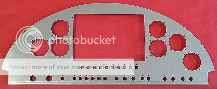
I already have the engine - a rebuilt Lycoming IO-320 which will be running P-mags; prop will be an MT 2-blade. Simple VFR panel with minimal instrumentation. Electric flaps and elevator trim. My only luxury so far has been a Bell tail-wheel fork, DM lightweight tail-wheel and tail-lynx linkage.

I already have the Rocket fastback bulkhead tops, rear top deck is to come. Canopy etc will be from Todds.

Here's a couple of shots of how NOT to do it:

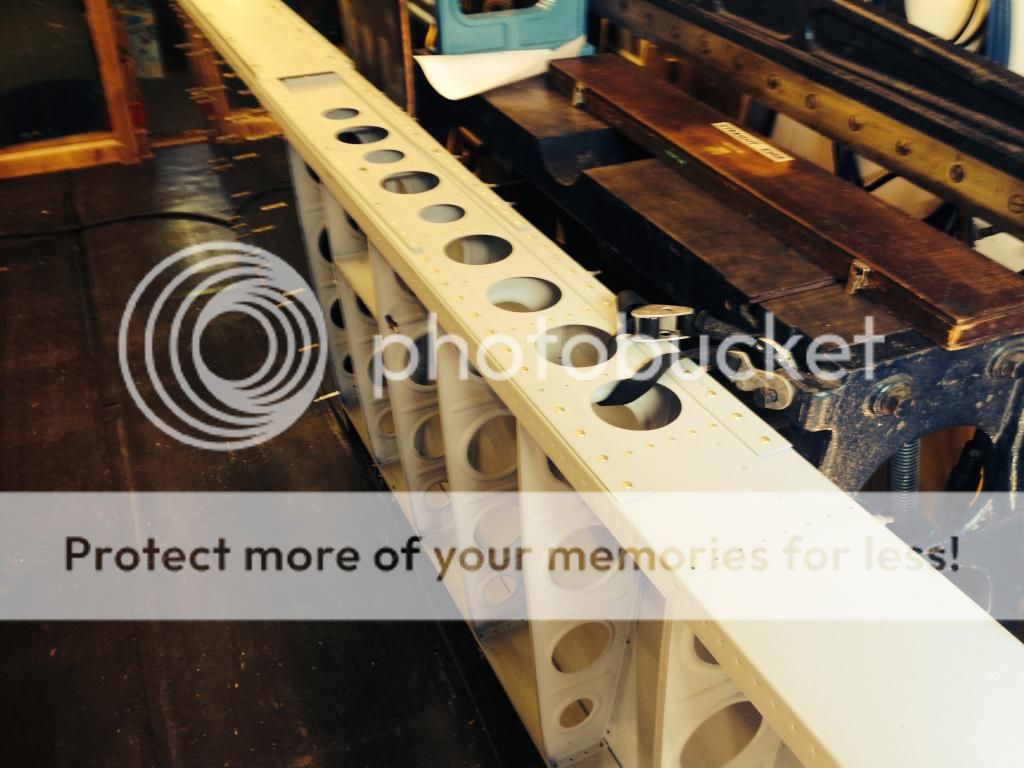
See the holes in the rear spar flange - they should be countersunk for the fuel tank flange - but were drill full depth so when the screws were tightened up, the nut plate was being pull up through a 5/16 hole! Vans do not have a fix for this - the spar is junk.

IMG_0201.jpg


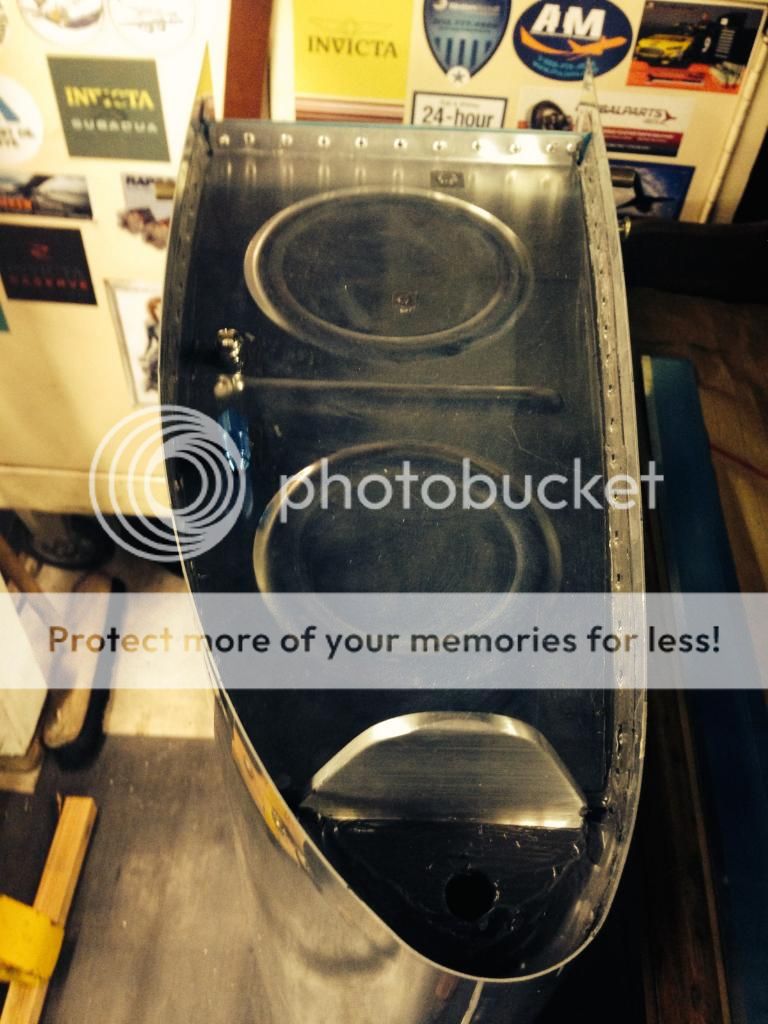
Shipping damage - tail-wheel mount not secured - remember to do this BEFORE you take your baby from the workshop to the hangar!

DSC_0053.jpg


Poor edge distance - in fact - missed altogether!
IMG_0362-1.jpg


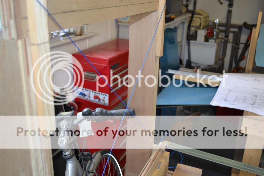
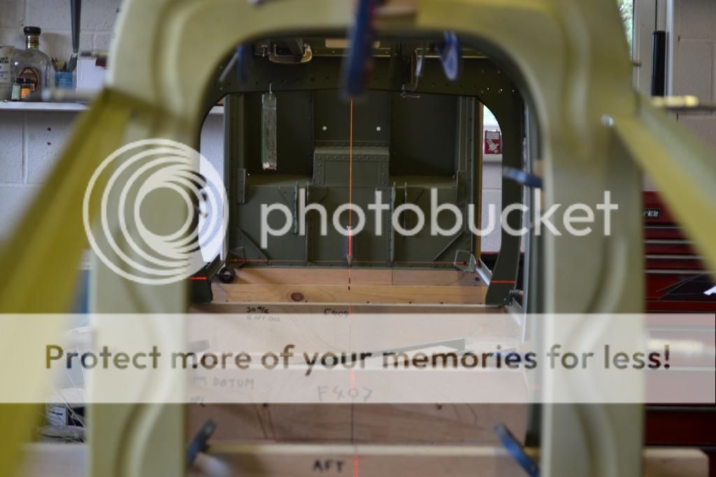
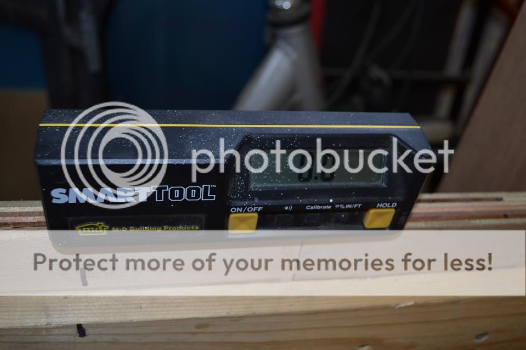
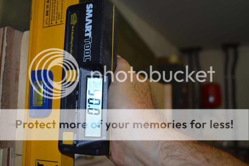
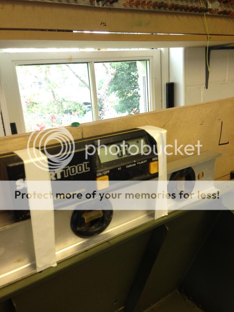
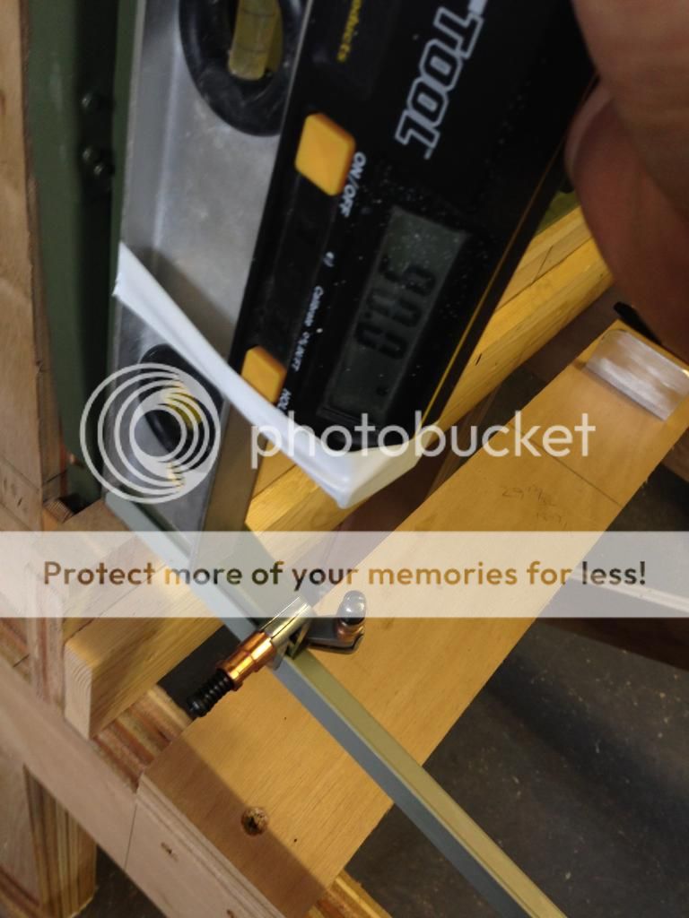
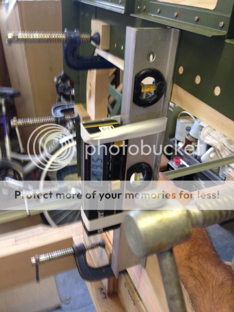
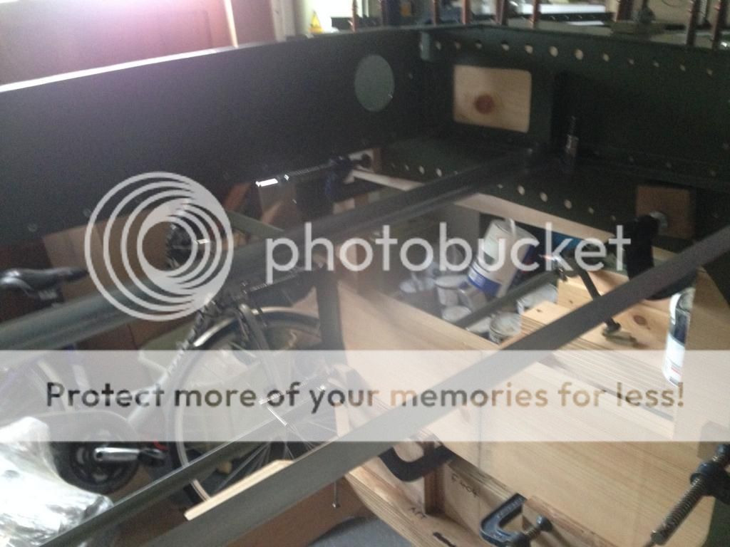
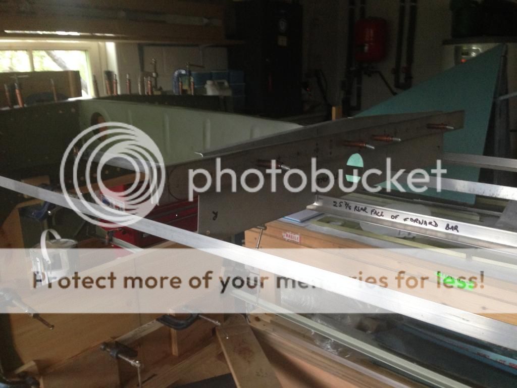
Here is my jig - 3 sheets of one inch thick, 8x4 plywood, so it should be stable. Glued to workshop floor. Accurate in pitch and roll to within 0.1 of a degree, so I was pretty happy with that. Cross checked all measurements several times and it seems to be square and accurate for bulkhead location.

IMG_0456.jpg


Most of these photos have been up before for one reason or another. I'll put some new ones up later of the various parts, now painted so that the interior will be the same colour as a P-51.

Hopefully there will be some useful info on here for other -4 and especially FB builders to add to the excellent documentation from Axel and others.

Chris
 
Last edited:
Hi Chris,

Is there much to do in the way of modification paperwork with the LAA for the fastback?

I would be interested in building my -4 as fastback when it arrives provided that it is not too onerous to get through the LAA.

I already have a few mods up my sleeve that I will have to put through them.

Simon
 
7 P's ...

also work...right now I'm prepping my right wing fuel cell for pro-seal, hopefully on Monday! yippeee:rolleyes:

Will post some pictures as I progress
 
Wow thank you for posting those pics! They make me feel so much better about my work and my little screwups.
 
Wings nearly completed

Sometime since I started this thread so here is an update.

Wings are nearly done - both fuel tanks done, spars riveted up, top skin on the other, leading edges all done and ready to rivet. Should be done by the end of the month.

Lots of little discrepancies in the plans, lots of little things that I would do differently next time. But at last a pair of wings that I'll feel safe to sit on top of!

Set of ribs, ready to go:

IMG_0578.jpg


Wing panel

IMG_0577.jpg


Fuel tank. I put flop tubes in both wings - fewer holes to cut and drill, hence less risk of leaks

IMG_0579.jpg


I'll post some more photos of the finished panels in a bit.

Along the way I have designed and had my panel cut by Bill at Upnorth - lovely job and a very easy process, with lots of help and input from Bill.

IMG_0557.jpg


In the meantime - back to the fuselage.
 
Last edited:
flop tubes in both tanks

Nice posts and I am glad to see another -4 under contruction.

I saw you mentioned having flop tubes in both tanks.

I know its already done but did you consider that hose has a service life versus the metal pick up, it has an o ring cushion on the bob weight that has been know to deteriorate and fall off causing the chamfer in the weight to score the bottom skin of the tank,there isn't a prescreen on the flop tube, and you need to be careful about how you install it so that it never gets hung up in the wrong position. ( you always know the standard pick up is at the lowest corner of the tank barring installation error.)

the flop tube is heavier.

Its sort of standard practice to only have one flop tube for some of the above reasons.

Chris Murphy
 
Flop tube service life.

Chris - thanks - no, I didn't know that.... Well, its done now. I'll have to live with it for a while. Realistically if I do 200 hours a year I'll be doing well but I will need to build that into my inspection regimen at some point.

Chris
 
Firewall set up

Today I spent a fair amount of time getting my firewall set up square and true on the jig. I could tell early on that something wasn't quite right. Finally realized I could place the engine mount onto the jig and check that way.... Found about 1/4" adrift at the top right or bottom left mounting. I went back and rechecked all of the jig. Finally I found that the right hand upright (so for the left side of the firewall when the plane is upright) was plumb vertical at 90 deg on my digital angle meeter. But the left hand upright was at 89.7 sloping aft - seemed to little to make such a difference, but after more measuring I had to conclude that what seemed like a trivial error was the problem. I planed off some of the upright to get it plumb vertical, re-positioned the mount and WOW - got it right

Firewall is now screwed in place to the uprights.

I had initially checked the verticals using the crossed string method - but I think this isn't sensitive enough.

At the close of play (cricketing term tho perhaps in baseball too??) everything was lining up - the plumb bob on the centreline of the firewall was even intersecting the laser line I use for checking that everything is centralized and level...

Here's some pictures.

DSC_0256.jpg


Crossed strings just touch - but didn't indicate the misalignment.

DSC_0264.jpg


Laser level - everything straight.

DSC_0263.jpg


Crosspiece for firewall to rest on - level

DSC_0258.jpg


Offending vertical support after application of plane and elbow grease

DSC_0265.jpg


You may just be able to see the laser on the plumb bob string indicating that the firewall is centralized.

So far so good I think.

I hope these notes and photos are helpful to others building these "legacy" kits. Its a lot more challenging than the -8 I built and I can't think why it took me over 2 years to build something so straightforward...!!!!

CHris
 
Am I brave enough to proceed.....?

Last post was 3 months ago. Wow, progress is slow. My previous RV-8 experience, I've decided, is not helpful as it has encouraged me to think that parts will be the right size and shape, whereas in this kit they mostly are not!

So I offer my 3 RV-4 construction rules - and probably they work for RV-3s and -6s as well.

1. Don't cut anything unless you have to in order to proceed.....
2. Don't drill anything unless you absolutely must ......
3. Don't build any sub assemblies until you are sure it will fit and that it might not be easier to build it in situ.

I built the F414 and F415 (seat rib assemblies), and have now taken them apart. Ditto F413 (battery box).

I'd previously managed to get the firewall completely square, verticals, horizontals, equidistant to the sides from mid-line datum points.

IMG_0712.jpg


IMG_0711.jpg


After a LOT of messing about getting the F404 spar box set up, I settled on the following method. Insert pieces of timber of the appropriate thickness. Clamp the top (bottom as jigged) in position the correct distance behind the firewall. Use some discarded pieces of angle to fix the top (bottom as jigged) of the F404 at the correct distance behind the firewall -front end is screwed to the verticals on the jig, rear end clamped to the F404 flange. The photos should make this easier to understand. To my delight (and surprise) I found the F404 angled to give the correct incidence of 0.5 degrees.

IMG_0724.jpg


IMG_0713.jpg


Then, having disassembled the F414 and F415, I cut new pieces of angle at the precise length to give the correct spacing between F404 and F407, and clamped the angle in place. Then I found I could easily mark the required position for the F406 (rear spar attachment bars).

IMG_0722.jpg


IMG_0726.jpg


So now, I think I am good to drill the F414s to the angles on the spar box F404, get the rear spar attach fixed in place, and fettle and fit the front lower longerons (top as jigged), and finish up the F413 battery box components. With that all out of the way I should then be able to work on back with the remaining bulkheads and start fitting the skins.... Once the side skins are in place I can finish up the F415 (lateral seat ribs).


So guys - before I commit myself to the drill, what have I missed, not checked or ought to recheck? Any other thoughts?

Thanks

Chris
 
Putting the wings on - all the little gotyas!

I haven't posted here for ages, although I have made a lot of building progress. I will answer some of the questions that I haven't dealt with and put some other info on the fuselage build in a separate post, as this post is intended to document what I have discovered about putting the wings on.

At the time of writing the wings are built, fuselage, empennage and all control surfaces complete and paint applied. The aircraft is now in a nice shiny hangar and the empennage had been mounted. So - on with the wings.

First problem was the splice plates. These are the four plates that are - supposedly - match drilled to size along with the wing spars ans the F404 bulkheads. They are all engraved with their location - top or bottom, forward or aft.

I knew that the bottom aft plate had to be "built in" , in position behind the F404 because of the two longitudinal former that run under the seats. What I hadn't realised was that the plates are not completely symmetrical - - so I had built mine in very neatly but the wrong way round. I realised this error when I tried some trial fitting of hardware store bolts and they just obviously weren't right. Cue bout of swearing.Out with my trusty Dremel and I managed to slightly enlarge the slot that the plate lay in so that it could be extracted, reversed and reinstalled.

Second problem - while I had all four plates available I checked that the holes were all the right size and not blocked with any primer. They were slightly undersize, I think just because of some primer. The hardware store bolts were very tight. Engineering advice was some gentle cleaning with a tapered reamer by hand, not in a drill. Pleased I did that.

Problem 3. I thought I would check all the holes in the F404. More paint. More gentle reaming.

Problem 4. No paint on the holes in the spar - surely they will be right. Nope, they were distinctly undersized, which I don't understand. Not even the hardware store bolts would fit through. I was really concerned about this problem and I do not understand how it could have arisen. The local (aircraft) engineering shop loaned me a reamer that was adjusted to be 3-4/1000 less than 3/8", and I was able to clean out the holes and get a nice fit with the store bolts - still had to be tapped through with a hammer, much more like what I remembered with my RV-8.

Finally - after about 3 days' full time work - the moment of truth. The stub spar slide nicely into place (bit of grease to help it on its way) and the rear spar slide smoothly into place between the two ears. I was able to tap the store bolts through the splice plates, bulkheads and spars.

I will need to take the wings off again to finish a few minor tasks, install the aileron push-rods, the holes for the screws that attach the underside of the wing root to the little extensions of the fuselage floor, and then will put in the close tolerance bolts that will be kept on dry ice until they are needed. I suspect they will still need a more generous bit of persuasion from the hammer.

So the lessons are:

Build in the bottom aft splice plate during the fuselage build but make sure that its the right way round. The engraving for location is on the outside.

Make sure the various holes are clear of paint.

Check that the size of the holes is indeed 3/8", if not - take advice and deal with the problem before trying to assemble.

Finally - I was very wary of applying a reamer to any of the wing mounting holes. However everything was measured, checked and did indeed seem to be substantially undersized. The splice plates were probably correct with just a bit of primer in the way.. I concluded that the drilling/reaming process was never completed. Very surprised by that.

More to follow.

Chris Mitchell
 
I am going to be doing this step in a few months so I read your post very carefully. My understanding is that the spar splice plate bolts that tie the whole thing together are "close tolerance" bolts. What does that mean exactly? I'm not sure, but I intend to find out before I enlarge any holes. My understanding is that they are supposed to be a tight fit, like you need to tap them in. What I will do, having read your post is find out the specs, measure the bolts and buy or borrow some gauge pins to measure the holes. I hope the specs are on the plans. None of my splice plates are in the fuselage, which is finished. I am suppressing the urge to panic. I will pull them out and check them.

Are there markings on bolts which identify them as close tolerance?

Thanks for posting. I will be following your progress closely.
 
Last edited:
Question?

Do you have a builders manual? Are you using it?
Are you following it and reading through each section before you start work.

I built -4 over 20 years ago and I recall the manual was very detailed about the types of problems you have had.

Cm
 
Thanks Scott, I will check for the triangle.

Chris, the 3/8” holes are supposed to be reamed to 0.374, so one thou under nominal size. So a hardware store bolt very likely should NOT fit.
 
Thanks Scott, I will check for the triangle.

Chris, the 3/8” holes are supposed to be reamed to 0.374, so one thou under nominal size. So a hardware store bolt very likely should NOT fit.

I have found most general bolts to be .003 - .004” undersize. I have seen .0025” under once, but never .001.

Larry
 
Last edited:
Back
Top