Hi all,
I'm having a bit of trouble figuring out the relative position of a few parts. The parts in question are:
- F-1073-R and F-1073-L Side Skins
- F-1078 Forward Bottom Skin
- F-1079 Aft Bottom Skin
- F-1011 Bulkhead
- F-1047E-L and F-1047E-R Stiffeners
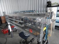
The plans first had me match-drill the stiffeners and have them clecoed to the side skins. Next, page 10-8, step 1 instructs to cleco the F-1011 Bulkhead and F-1079 Aft Bottom Skin to the F-1078 Forward Bottom Skin and the F-1073-R Right Side Skin. What I am unclear about is the position of the F-1047E-R stiffener in these parts. The plans seem to imply that the stiffener stays where it is, right next to the F-1073-R side skin. Then Figure 1 on the page depicts the F-1079 Aft Bottom Skin clecoed to the inner side of the the F-1078 Forward Bottom Skin and the F-1073-R Side Skin. Finally, the F-1011 Bulkhead is clecoed to the inner side of the F-1079 Aft Bottom Skin. So the sandwich would be (outer-to-inner): F-1073-R, F-1047E-R, F-1079, F-1011.
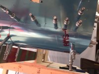
However, the way the flange is cut out for this particular hole in the F-1011 Bulkhead is the same as the holes for the other two stiffeners - F-1047C-R and F-1047D-R. In these two other places, the stiffeners directly contact the bulkhead flange, and the configuration of the flange makes sense. But where there is F-1079 skin in the middle, the flange of F-1011 is not sitting flush with the skin.
Perhaps, the intended configuration is different: F-1073-R, F-1079, F-1047E-R, F-1011. In that case, the two skins are contacting each other, the stiffener goes over both skins and sits flush with the flange of the F-1011 bulkhead. But in that case, the F-1047E-R stiffener isn't sitting flush with the skins! The place where the stiffener transitions from one skin (F-1073-R) to two skins (F-1073-R + F-1079) makes a little bit of gap and it doesn't look right.
I would expect the plans to be specific about this, but they aren't. Another thing that confuses me is the order of assembly. The plans have you do the right side first, without the F-1079/F-1011 in place. Presumably, this includes drilling the aftmost hole of the F-1047E-R stiffener. You drill it through JUST the F-1073-R skin. Then you cleco the F-1079/F-1011 and do the left side. So when drilling the aftmost hole of the left 1047E-L stiffener, you drill through the F-1073-L skin, the F-1079 skin, and the flange of the F-1011 bulkhead. So it's not exactly symmetrical.
Sorry about the long description, but I wanted to be as specific as possible. Thank you in advance for your help.
I'm having a bit of trouble figuring out the relative position of a few parts. The parts in question are:
- F-1073-R and F-1073-L Side Skins
- F-1078 Forward Bottom Skin
- F-1079 Aft Bottom Skin
- F-1011 Bulkhead
- F-1047E-L and F-1047E-R Stiffeners
The plans first had me match-drill the stiffeners and have them clecoed to the side skins. Next, page 10-8, step 1 instructs to cleco the F-1011 Bulkhead and F-1079 Aft Bottom Skin to the F-1078 Forward Bottom Skin and the F-1073-R Right Side Skin. What I am unclear about is the position of the F-1047E-R stiffener in these parts. The plans seem to imply that the stiffener stays where it is, right next to the F-1073-R side skin. Then Figure 1 on the page depicts the F-1079 Aft Bottom Skin clecoed to the inner side of the the F-1078 Forward Bottom Skin and the F-1073-R Side Skin. Finally, the F-1011 Bulkhead is clecoed to the inner side of the F-1079 Aft Bottom Skin. So the sandwich would be (outer-to-inner): F-1073-R, F-1047E-R, F-1079, F-1011.
However, the way the flange is cut out for this particular hole in the F-1011 Bulkhead is the same as the holes for the other two stiffeners - F-1047C-R and F-1047D-R. In these two other places, the stiffeners directly contact the bulkhead flange, and the configuration of the flange makes sense. But where there is F-1079 skin in the middle, the flange of F-1011 is not sitting flush with the skin.
Perhaps, the intended configuration is different: F-1073-R, F-1079, F-1047E-R, F-1011. In that case, the two skins are contacting each other, the stiffener goes over both skins and sits flush with the flange of the F-1011 bulkhead. But in that case, the F-1047E-R stiffener isn't sitting flush with the skins! The place where the stiffener transitions from one skin (F-1073-R) to two skins (F-1073-R + F-1079) makes a little bit of gap and it doesn't look right.
I would expect the plans to be specific about this, but they aren't. Another thing that confuses me is the order of assembly. The plans have you do the right side first, without the F-1079/F-1011 in place. Presumably, this includes drilling the aftmost hole of the F-1047E-R stiffener. You drill it through JUST the F-1073-R skin. Then you cleco the F-1079/F-1011 and do the left side. So when drilling the aftmost hole of the left 1047E-L stiffener, you drill through the F-1073-L skin, the F-1079 skin, and the flange of the F-1011 bulkhead. So it's not exactly symmetrical.
Sorry about the long description, but I wanted to be as specific as possible. Thank you in advance for your help.
")