Working on the labeling for the panel and have a question for the P-mags. I am going with two P-mags and have four toggle switches grouped together, upper two for power to the mags lower two for P-leads, what should I label these switches? for those with p-mags what are you calling the power switch used to test the mag at low RPM. Space is very limited. Thanks, any help appreciated

Van's Air Force
You are using an out of date browser. It may not display this or other websites correctly.
You should upgrade or use an alternative browser.
You should upgrade or use an alternative browser.
Question about the P-mags
- Thread starter mattsmith
- Start date

erich weaver
Well Known Member
I labeled mine "L IGN TEST" and "R IGN TEST"
erich
erich
I have always found that labeling the switch with it's actual function is almost always the best choice. In this case, it isn't a "Test" switch - it is a power switch - it turns power on and off to the P-Mag. So label it "Power" and the positions "On" and "Off" (or it could be argued "On" and "Test").
Think about a complete stranger getting in the airplane, and wanting to know what did what - would it make sense to him/her? Would they need a briefing to understand what each switch did, or do the labels stand alone?
I went with circuit breakers for the power, and they are "L Ign" and R Ign" respectively. The P-Lead switches are labelled "L Ign" and "R Ign", with the positions "ON" and "OFF".
Paul
Why not "L P-MAG PWR" and "R P-MAG PWR"? This most accurately describes what the switch does. How you use the switches, may constitute a test of the ignition system. If space is an issue, just label P-MAG PWR once and put L and R directly above each switch. YMMV
Bevan
RV7A wiring
Bevan
RV7A wiring
Last edited:
Toobuilder
Well Known Member
Sounds WAY too complicated
How often do you intend to "test" them? In several years with my Hiperbipe, I have only tested mine a few times (using a breaker). I also use my standard mag (key) switch for the normal L/R/Start function. With the -8, I went one step further - power is wired to the main buss, and the "test" switch is my master switch. On the odd chance that I wish to test the function of the internal generator, I simply turn off the master to the airplane while it is idling and cycle through the key switch to isolate each ignition. For normal ops, it's exactly like any other airplane out there.
How often do you intend to "test" them? In several years with my Hiperbipe, I have only tested mine a few times (using a breaker). I also use my standard mag (key) switch for the normal L/R/Start function. With the -8, I went one step further - power is wired to the main buss, and the "test" switch is my master switch. On the odd chance that I wish to test the function of the internal generator, I simply turn off the master to the airplane while it is idling and cycle through the key switch to isolate each ignition. For normal ops, it's exactly like any other airplane out there.
Last edited:
lostpilot28
Well Known Member
Matt, you mentioned that space is "very limited". Why not go with 2 switches instead of four? I followed Bill Repucci's wiring diagram and have had great results. I believe the switches are s-50, but I don't recall. If you do a search you'll find his diagram. If you can't find it, let me know and I'll send you mine.
apkp777
Well Known Member
How often do you intend to "test" them? In several years with my Hiperbipe, I have only tested mine a few times (using a breaker). I also use my standard mag switch for the normal L/R/Start function. With the -8, I went one step further - power is wired to the main buss, and the "test" switch is my master switch. On the odd chance that I wish to test the function of the internal generator, I simply turn off the master to the airplane while it is idling and cycle through the key switch to isolate each ignition. For normal ops, it's exactly like any other airplane out there.
Mine's identical. I "test" mine only once a month or so. I think the Klixon breakers are good for about 3-5000 cycles, so I think in 20-30 years I will need to replace them.
Toobuilder
Well Known Member
Matt, you mentioned that space is "very limited". Why not go with 2 switches instead of four...
... how about "one" instead of "five" (the fifth being the starter) Just wire them up to the standard key switch and be done with it.
tonyjohnson
Well Known Member
P mag switching
Steve Sampson from the UK has devised a very nice method of providing the normal operating plus test function using one switch per P mag. It is not inconsistent with the recommendations of Emag air, although they do not endorse this method.
It can be found here:
http://gikonelectrics.blogspot.com/2008/09/p-mag-wiring.html#links
It utilizes the 2-50 switch, which I can only find at B&C. I don't mind paying the $18 or so for the switch, but I feel a bit put upon by paying them $8 to ship it. If you use this switch for this purpose be aware that you will have to install it with the keyway down to end up with the "test" position up as in Steves design. Keep that in mind when you drill the hole in your panel for the keyway tab.
I have not seen Bill Repucci's method, perhaps it is similar.
To answer your question: Four SPST switches in a row, labels above the switches.
---------------IGNITIONS------------------
L - POWER - R L - SPARK - R
Don't use the progressive-on S50s. I once went that route and subsequently changed the panel. There's no way you can properly test P-mags without causing a reboot while the engine's running. That's very hard on the ignition, and totally negates having tested it. There are plenty of threads on this issue.
"Power" is the +12. "Spark" is the p-lead (ground). Grounding tells the P-mag to stop sparking, but the electronics are still fully awake.
John Siebold
Toobuilder
Well Known Member
... There's no way you can properly test P-mags without causing a reboot while the engine's running. That's very hard on the ignition, and totally negates having tested it...
Not sure I understand what you?re getting at John ? The ?test? is to determine if the internal alternator is working or not. This is performed (per Emagair) by removing power from the ignition while the engine is running. Removing the power can be done by opening a separate ?test? switch, pulling a breaker or fuse, cutting the battery cable with an axe, or like I do, simply turn off the master switch. The ignition does not know what method was used; only that it is no longer getting power. Whatever means you use to cut power, if the engine quits, then you have a problem ? otherwise, the alternator picks up the load and the ignition never reboots - go fly.
Am I missing something?
I should have asked sooner, I like the idea of one switch doing both functions but I have already cut the panel and had it powder coated so to go back and use one switch I would have to make a plate and have it powder coated to match the rest of the panel. The powder coater?s minimum is $65 to do a 3"X4 plate.
I think I can get ( L MAG PWR and R MAG PWR) above the switches, thanks Matt
I think I can get ( L MAG PWR and R MAG PWR) above the switches, thanks Matt
RVG8tor
Well Known Member
Used buttons
I wrestled with not using switches for power, in the end I thought the CB pull force was too much and the switches were cheap. This is how I labeled mine, I used Decal Pro to make the decals after laying it out on TruboCAD
Buttons are the Normally Closed, as in alway on type. Push button and takes 12 power from P-Mag for the test.
Cheers
Toobuilder
Well Known Member
I should have asked sooner...
Since you are stuck with a non standard ignition control configuration, at least try make it intuitive. For the "power" switches (toggle type), I'd suggest "NORM" and "TEST" (spring loaded to "NORM"). For the "ignition" switches, "On" and "OFF" works. If you still have the option, I think a push button (like Mike shows above), or a C/B should be used for "power".
Just curious, are you still using a key switch for the starter?
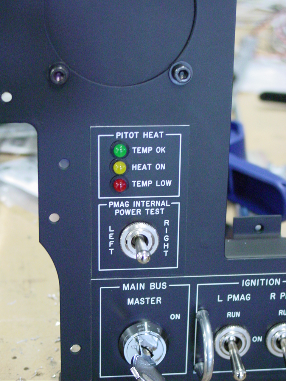
Yet another iteration, which maintains the separate test function and ability to control ship's power to each Pmag, using 3 toggle switches in total.
Pair of switches, DP3T on-on-on, one for each ignition:
Down ("Off") - power off, plead grounded
Center ("On") - power on, plead grounded
Up ("Run") - power on, plead ungrounded
One switch, DP3T (on)-on-(on), serves as test for both ignitions. I mounted this switch rotated 90* so the actuation is left-right rather than up-down, and it's spring-loaded to the center position:
Center - Power passes to both ignitions
Left - breaks power line to left ignition
Right - breaks power line to right ignition
(placard: "Pmag Internal Power Test - Left - Right")
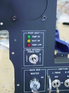
I believe this is in keeping with the methods outlined by Emagair, though I think that any of these switchologies will need a checklist/POH section to explain the method of testing the internal power. ("Switch off plead of opposite ignition, then actuate test switch")
Pair of switches, DP3T on-on-on, one for each ignition:
Down ("Off") - power off, plead grounded
Center ("On") - power on, plead grounded
Up ("Run") - power on, plead ungrounded
One switch, DP3T (on)-on-(on), serves as test for both ignitions. I mounted this switch rotated 90* so the actuation is left-right rather than up-down, and it's spring-loaded to the center position:
Center - Power passes to both ignitions
Left - breaks power line to left ignition
Right - breaks power line to right ignition
(placard: "Pmag Internal Power Test - Left - Right")
I believe this is in keeping with the methods outlined by Emagair, though I think that any of these switchologies will need a checklist/POH section to explain the method of testing the internal power. ("Switch off plead of opposite ignition, then actuate test switch")
SmilingJack
Well Known Member
Switch Layout
mine are kind of like "Nemo's"
4 switches:
P-Lead....P-Lead....12v IGN.....12v IGN
.....L.........R...........PWR L.......PWR R
when you switch each switch "OFF" the top of the switch reads "OFF"
Brad at Emagair suggested this so that during run-up I could check each pmag to see if they are running and to check the internal alternator.
During run-up I turn off the Left P-lead (grounds it) and then I turn off the R IGN PWR. If the engine is still running the internal alternator is suppling the power - then do the same thing for the other side.
They are "Honeywell" switches I got from "Stark Aviation".
Good Luck!

