What's new
Van's Air Force

Don't miss anything! Register now for full access to the definitive RV support community.

RV 14 Plan "Gottchas"

HeliCooper

Well Known Member
If you are having issues gaining access or editing the spreadsheets please leave a comment in this thread and I will solve the problem. Thanks

Common traps and mistakes:https://docs.google.com/spreadsheet/ccc?key=0Ahl5Xwgv8uaRdGR3VDR2MkNBQTA5WXQ0dkxaZGg3RFE&usp=sharing

Inventory sheets:https://docs.google.com/spreadsheet/ccc?key=0Ahl5Xwgv8uaRdHdTTTZka1ZDSXoyMWthSVNJTUZ0TXc&usp=sharing

All inventory lists that I have available are on the above link. Please see the tabs towards the bottom of the page to switch between different kits.

Thank you to user jswareiv for the empennage kit, user Marabou for the wing kit, and user GeraldC for bringing the wing kit spread sheet to my attention.
 
Last edited:
Feel free to start populating this guys. I don't have my empennage kit yet so unfortunately I have nothing else to contribute at this point.

Thanks Mike for getting this...um stuck. :)
 
Thanks

Great idea! As a first time builder (kits not even in the mail yet) I would reallllyyy not learn the hard way EVERY time!

Cheers
 
Feel free to start populating this guys. I don't have my empennage kit yet so unfortunately I have nothing else to contribute at this point.

Thanks Mike for getting this...um stuck. :)

I've broken the ice. I'm quite literate with Office products for years but not with "online" services so I'm not sure if what I've done is okay. Since the page was blank with no headers, I took the liberty of naming these as I think is appropriate and consistent with what you have suggested in the first place.

I look forward to see inputs from other contributors. !! :D
 
Thank you Marc for getting us going. The idea of adding VAF reference links is perfect! I only changed one thing. I added the Kit before your page numbers. This will help with sorting later down the road when we have Empennage, Fuselage, and Finishing kits all going on as well.
 
Last edited:
I received a reply from Ken @ Vans that there was an error on page 09-15 about scuffing under the E-1008 ribs. Since no bonding is required in this area scuffing is not required. Only the areas where bonding will occur need scuffing. I've added this to the Gotchas list.
 
Done and done.

If everyone wants to move forward with this then I created a document. Anyone that clicks on the below link can view and edit the document. If we can get a moderator to sticky the link at the top of the RV14 forum it should be an easy find for everyone.

As for formatting I will look to you building for what you think is the most logical solution. I was thinking the first column can be the section number/step number and then next column could be the description of what to watch out for. This way I can periodically, once a week or so, go into the document and reorder the steps so that it will be easy to find. This way when you are on your way out to work on a certain step you can you scroll to the area and see if there are any common problems. If we can all decide on a format here I will insert at the top the column headings and instructions for adding to the list.

Let me know if there is anything else I can do.

https://docs.google.com/spreadsheet/ccc?key=0Ahl5Xwgv8uaRdGR3VDR2MkNBQTA5WXQ0dkxaZGg3RFE&usp=sharing

Really a slick idea......would be great for each of the RV model threads..
 
Possible Error?

Ok please correct me if I'm wrong, on page 06-04 step 4, you're told to dimple the flanges of all internal spars and ribs with the exception of VS-707? This makes no sense. Given the fact the plans tell you it dimple the VS-801 skin for 426 rivets. I think this may be a minor error?
 
Small Bag reference to plans sections?

I have looked at the spreadsheets and can't find a list that correlates the small bags to plans sections. I can't really tell by looking at plans and bag inventories if there is a one to one or one to two correlation.

Several other RV guys said empty the bags in to the tackle box divider trays, label the compartments and pick parts from there. Seems the common practice but I can't believe that a kit as well engineered as this isn't organized that one last step. I just can't find the documentation.

Information or opinions.
 
There is no correlation between the bags and the sections of the kit. The first bag you dip in might also be the same bag you pull from for the last section of that kit. One reason for this is that parts that look the same and are used on the same part are put into different bags so you can figure out which is which.
 
Bag correlation

Aha.... part of the 51% rule I suppose. The tedious hours sorting through things.

The tackle trays and baby food jars it is. Now I have something to do between getting my vertical stab deburred and my primer coming. Where was that label maker my wife had?

Thanks.
 
Addition to plan Gottchas

Step 7 on Page 08-02 asks to scuff the powder coating on the hinge brackets for HS. Step 3 on page 06-04 after "disassemble and deburr parts" should include " Scuff the powder coating on the hinge brackets if you plan to paint them". Being new builder I didn't do it for VS because there is no such step in the plans for VS. Now that they are riveted in place it will take extra time to get it done.:(
 
Pg 06-04 Dimpling Question - Emp. Fairing Attach Locations

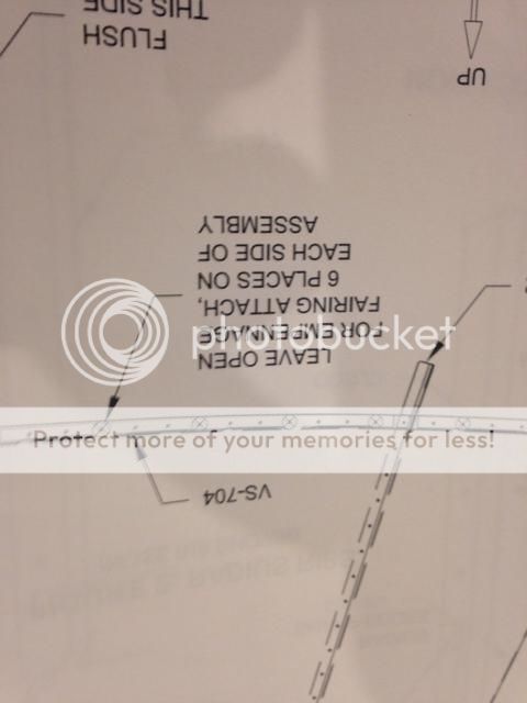
Do you dimple the places in VS-704, VS-705 & VS-801PP where it says LEAVE OPEN FOR EMPENNAGE FAIRING ATTACH, 6 PLACES ON EACH SIDE OF ASSEMBLY? I put tape over the holes and left them alone, but I am about ready to rivet the VS together.
 
Last edited:
It's been a while but the emp fairing is made of glass and you countersink the glass. So those holes to attach it do not need dimpling.
 
I can edit the inventory, but not the gotchas page. I wonder if someone has it open and only the first person to open can edit. Don't know.

I did add all the inventory from the bags to the empennage inventory list last week.
 
Someone altered the sharing settings. I have reset them so if you get to the spreadsheet through the link provided here you have authorization to edit the spreadsheet.

Thanks for bring this to my attention.
 
It worked that time. Thank you.

I added the mistake I made on page 09-08, step 6. I feel stupid, but at least smart enough not to make that same mistake again! :D

By the way, this list is an awesome idea! I reference it before each new chapter.

Chuck
 
06-04 (VS) Step 5

This is for the "gotcha" section:

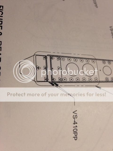
I just heard back from Vans and there is a missing rivet in the plans. The VS-410PP upper bracket only has 5 rivets called out. The bottom middle hole should have a rivet. This will be coming in an updated plan revision. Maybe this has been posted before, but I could not find it.

The issue is that the doubler is CS on the doubler and dimpled on the spar. Kind of hard to do that after the fact. I guess you could just CS later.

 
06-04 (VS) Step 4

This is a reference for the "Gotchas" section.

The holes which the plans say to "leave open" DO NOT get dimpled. The holes are for the fairing (which will come in the finishing kit) and the fairing holes will be counter sunk (CS).

 
I went out to the garage and that hole does indeed looks like is it used to align the VS when attaching to the empennage. I re-asked the question to Vans about the rivet. I will let you know what I hear back.
 
I got the same answer from vans. The hole in question is NOT an alignment hole. It does line up with a hole on the spar, but the flanges in the rear spar are a snug enough fit with F-01412 that the hole lines up anyway.


here is the quote from an email from Vans:

"I clarified with Engineering to go ahead a CSK and rivet that one hole the same as the rest of them on the VS-410PP. There will be a plans revision forthcoming. Thanks for bringing this to our attention..."
 
This is for the "gotcha" section:

I just heard back from Vans and there is a missing rivet in the plans. The VS-410PP upper bracket only has 5 rivets called out. The bottom middle hole should have a rivet. This will be coming in an updated plan revision. Maybe this has been posted before, but I could not find it.

The issue is that the doubler is CS on the doubler and dimpled on the spar. Kind of hard to do that after the fact. I guess you could just CS later.


The support person that helped you was mistaken.
This is not an error... the hole is intentionally left open and a future plans update will make note of that. Because of that, the parts at this hole location do not need to be dimpled and countersunk. If they have been, it is not a problem.
The hole is used as a alignment reference hole when fitting the stab to the aft fuselage later in the build.
 
This is a reference for the "Gotchas" section.

The holes which the plans say to "leave open" DO NOT get dimpled. The holes are for the fairing (which will come in the finishing kit) and the fairing holes will be counter sunk (CS).


The note just prior to the Step which begins the instructions to dimple says

NOTE: Tape over holes that do not receive
rivets at this time to avoid accidentally riveting
these hole locations. See Figures 1 and 2 for
locations.


The intent is that if you are not to rivet them, you are also not to dimple them.

I will suggest that the note be changed to
NOTE: Tape over holes that do not receive
rivets at this time to avoid accidentally dimpling or riveting
these hole locations. See Figures 1 and 2 for
locations.
 
Can I just flatten out the dimples with a flat squeezer set then?

It is best to leave it as it is. It will not cause a problem.
When the hole gets final drilled for the emp. fairing attach attach screws, it will get enlarged enough to remove the majority of the dimple.
This is a much better result than the distortion that will occur in the skin surface if you try and flatten out the dimpled (stretched) material.
 
"Match Drill", this is a flag to take heed and pay attention . . . .

. . . and to not take the diagrammatic illustrations in the assembly instructions literally.

I finally have learned a major lesson, that kind of lesson pilots learn about flying in a few seconds and that you had previously heard about but only now take heed of after first hand experience.

I had heard from a few other RV builders and in Van's Section 5, something like this >> "Read each assembly section and page a few times and follow each step explicitly."

And, if there is not an alert (NOTE) in BOLD >> highlight the match drill instruction and the parts that you match drilled. Mark sufficiently the parts so that when they are disassembled, they can for sure be reattached correctly.
 
Last edited:
Gotcha 08-02, Rear Spar

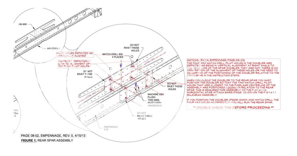
Attached is a better description of the Plan Gotcha; RV14, Empennage, pg 08-02, Rev 0, 4/15/13.


Hind sight is close to 20/20 >> The four 1/8" pilot holes are in the rear spar and the match drilled #30 holes go into the spar doubler. The fault of drilling the holes the second time into the rear spar was clearly mine in not marking the parts when I disassembled them. It was when I reassembled them, inadvertently rotating the spar doubler and seeing that the four holes in the doubler did not have corresponding holes in the spar, I then re-drilled into the spar the second time (BIG mistake). It was my bad for ruining the spar. This error may have been avoided if there had been a warning about the unique alignment and/or it had been illustrated accurately. Live and learn.

Anyhow, much thanks to Van's for going the extra mile in helping me fix my error.
 
Last edited:
Page 10-13: Attaching the F-01407 Bulkhead to the bellcrank ribs

Revision 1 adds a new step 1 to this page. 470AD4-4 rivets are called out to attach the bulkhead to the bellcrank rib/battery angle assembly. I found that the nutplate on the battery angle really crowds access to the bottom rivet hole. If I had it to do over again I would leave that nutplate out (page 10-12) until I got the bulkhead attached and then install the nutplate. I guess that would make it Step 1A on page 10-13.

Also, on page 10-14 step 11 (optional) you are instructed to dimple the #27 holes in the left and right skins per figure 2. The illustration callout says "6X DIMPLE #27 HOLES" and it does not address the two upper #27 holes on each side. What did the front-runners do here? Looks like they need dimples too.
 
Either way will work

As for page 10-14 step 11 (optional) where you are instructed to dimple the #27 holes only 6 holes on each side, all but the top two, this really caused me to scratch my head as well.

Looked ahead and saw where the plans had you to machine countersink the completed assembly at page 10-20, step 3. Why in the world not do this at the same time as the other six? And I sure didnt want to risk having that knife edge in the skin holes.

So I did all 8 together in the "normal" way, and then began to worry I may have messed up. Contacted Vans's, and much to my relief, they said I will be fine. Still did not understand why the deviant procedure however.

Figured it out when I went to rivet on the nutplates behind these top two sets of holes. Ah ha!!! the #27 dimple on the backside of the skin is slightly larger than the #27 countersink in the longeron, causing the skin to pucker out ever so slightly.

Story ended well. Simpy used my squeezer to compress these puckers. Placed one set on the back side of the nut plate, and then pressed the pucker inward using the opposite set to flatten it back. Seemed to sort of push it into the longeron countersink. Worked great.

Just shows Vans really knows what they are talking about. As if I doubted? :eek:
 
Page 10-27, rev 1: Flush rivets added?

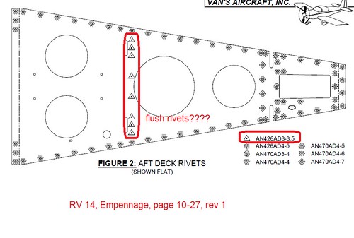
Rev 1 on page 10-27 calls for flush rivets in the holes circled in red for the aft deck. This callout was changed from dome heads at a -4 length in Rev 0 to flush rivets at -3.5 length in rev 1. I have a feeling they meant to only change the length, and not the style to flush. Nothing in plans called for dimpling or countersinking these holes. Is this a typo in Rev 1 and should be calling out dome head rivets here?

16665642031_6b573d314a.jpg
 
Last edited:
fairing nut plate locations

On page 10-20 there is a nut plate location next to the leftmost nut plate and another one off the picture. The instructions don't show nut plates in those locations, but looking at the fairing installation section, it looks like nut plates are needed in those locations. What am I missing?
 
Those screw locations correspond to the fiberglass empenage fairing which needs to be match drilled using the holes in the aft fuselage, so the nutplates do not get installed until after that has been completed.
 
regarding 10-27, Rev 1,


Is the correct rivet FLUSH ????

I am about to get to this point on the emp.

Sorry, I forgot to follow up on this.
470AD4 rivets is correct..... there is no reason for flush rivets in this area ( a future plans revision will reflect the change).
 
I cut my J channel stringers about 1/4" longer than the plans, then trimmed the long end after locating and match drilling. If you cut it per plans it will barely have ED on the most inboard and outboard rivets.
 
Getting started

I am getting ready to start building the RV14 in a couple of weeks. Thanks to all those posting the gotchas. That is some really good info that I am sure is going to come in handy!:)
 
I am getting ready to start building the RV14 in a couple of weeks. Thanks to all those posting the gotchas. That is some really good info that I am sure is going to come in handy!:)

Hopefully it won't even be needed.
As early builders found plans errors, corrections were made.
 
RV14 build

John, welcome aboard. I have a 14 tail kit in progress in East Orlando by UCF. Private message me and we can connect. Having another 14 in town will be a good thing.

I am getting ready to start building the RV14 in a couple of weeks. Thanks to all those posting the gotchas. That is some really good info that I am sure is going to come in handy!:)
 
Mine did not nest as nicely as yours, but the top picture is what I believe is correct (based on the pictures I looked at in my collection).

The long one goes on top of the shorter one. Hopefully I have that correct on mine :)
 
The bottom picture is correct. This is the same orientation as when you matched drilled them on the spar. The J channel long is against the upper skin at the overlap so it is 'on top'.
 
The bottom picture is correct. This is the same orientation as when you matched drilled them on the spar. The J channel long is against the upper skin at the overlap so it is 'on top'.

Correct.

Think of the one j-stiffener as acting as a shim for the other to account for the step off of the underlaped main wing skin.
 
Last edited:
Back
Top