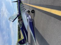
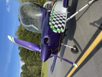
What's new
Van's Air Force

Don't miss anything! Register now for full access to the definitive RV support community.

Show us the status of your 14/14A project

Love that spinner!

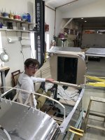
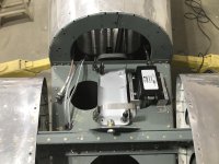
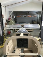
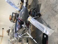
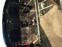
Hung my Thunderbolt IO-390 EXP119 a few months ago. This weekend i mounted the Prop. I'll get more shots after I screw on spinner and remove the plastic - this is just a teaser. Thanks to Jeff and team at TB for beautiful engine.
 
Anyone else notice they are using internal wrenching nuts on the cylinder hold down nuts? Is the Thunder Bolt IO-390 a narrow deck engine?
 
Almost ready for airplane noises!

Fuse is finished. Just in time to find out about the sweat snafu for some of the QB wings. Hopefully not mine since i was planning to start assembling them next month.
 

Attachments

  • 122C8D8A-D354-437B-8339-20B6D6D15A3B.jpg
    122C8D8A-D354-437B-8339-20B6D6D15A3B.jpg
    396.9 KB · Views: 555
  • 35C7AD37-755F-4678-B9D6-BAF80878A580.jpg
    35C7AD37-755F-4678-B9D6-BAF80878A580.jpg
    330.2 KB · Views: 589
Now, Fuse is Finished!

3-2-2021. Fuselage is completed sans paint.

QB Wings are delayed due to Covid issues at subcontractor assembly plant and Van's redoing of primer, etc. No date available for packing. Ugh.

So, since Finishing Kit not scheduled to arrive until mid May, and engine and FWF not scheduled until July, I have time on my hands.

I guess I'll start planning/assembling the wiring and avionics. Just saw the post regarding the price increase at Vertical Power, so I ordered the PPS, VPX-Pro, and VPW-Pro WH. Saves $500. Wasn't planning this until later, but, gotta keep building!

Onward.

S
 

Attachments

  • Fuse Fwd to Aft View Completed.jpg
    Fuse Fwd to Aft View Completed.jpg
    326.9 KB · Views: 475
  • Fuse Aft to Fwd View.jpg
    Fuse Aft to Fwd View.jpg
    372.3 KB · Views: 439
  • Fuse Fwd Panel and Cowl.jpg
    Fuse Fwd Panel and Cowl.jpg
    411.6 KB · Views: 489
  • Farings Elevators, HS, VS.jpg
    Farings Elevators, HS, VS.jpg
    288.9 KB · Views: 460
  • Fuse Interior - Pitch Servo.jpg
    Fuse Interior - Pitch Servo.jpg
    238.5 KB · Views: 465
  • Fuse Front Cowl w:Adam.jpg
    Fuse Front Cowl w:Adam.jpg
    345.8 KB · Views: 502
No more “project” posts for me..... finished phase 1 AND have all of the wheel pants/fairings on. TAS this morning was 177kts at 2500 squared 6500 ft. Motivation for those still building.
 

Attachments

  • 52DB74ED-651A-4FD0-9530-F4D5DDDD808D.jpg
    52DB74ED-651A-4FD0-9530-F4D5DDDD808D.jpg
    541 KB · Views: 372
Hey Rockitdoc, your 14 is looking good, I'm building a standard RV7 kit in my hanger at KFNL, I think there is another guy building a 14 in FC but haven't seen any at KFNL.
 
Hey Rockitdoc, your 14 is looking good, I'm building a standard RV7 kit in my hanger at KFNL, I think there is another guy building a 14 in FC but haven't seen any at KFNL.

Thanks Bob.

My QB Wings will be late due to fabrication issues.

So, I'm pushing on with avionics. Building full-scale 'doll houses' out of foam and paper.

If this project doesn't work out, maybe I can join the modeling crowd.

Now, if I could just figure out where all those wires go........
 

Attachments

  • PAnel Model.jpg
    PAnel Model.jpg
    289.1 KB · Views: 359
Rockitdoc, I'm doing the same, working on my panel. I have the GRT Horizon 10.1, Sport EX7, safe fly ADSB-EchoDuat,
Stacked Remote VAL 2KR Nav and VAL 2KR Com
PS Engineering PRI30EX remote intercom
GRT EIS Remote model EIS-66R
TRIG TT22 remote Mode S transponder
Garmin GTR 200 stand alone com/intercom.( GRT don't have the SW for these yet)
Have these mounted but like you, where do you put all the wires.
 
Wiring Harness Begun

Since my wing kit is delayed I decided to begin the wiring. I bought the Common Harness WH-00125 from Steinair for $1149. It came yesterday and I began the process of figuring out where it went and how to get it there today. It's a very high quality harness, all labeled and terminated. However, there are two places on each harness (L and R) where connectors have to be removed to fit through the bulkheads. The first is the is where the harness meets the aft fuse harnesses because the Molex on the end of the harness won't go through the bulkhead aft of the flap motor. If you haven't finished putting in your elevator tubes, it would fit through, but I already had the tubes in and torqued and I judged disconnecting the Molex easier than removing the tubes. The other location to be removed is the end of the control stick harness. Not a biggie in my case, because I hate the micro Molex connectors that come with the harness at this location and would have replaced them with 0.062 Molex anyway.

Anyway, some photos of how well this harness is assembled follows. Stein does such a good job of locating every junction exactly where it needs to be as you can see from the photos.

Tomorrow, I'll put in all the split grommets and bore a hole where the LEMO connector will go, then connect up the Common Harness to the aft harnesses and start figuring out how to mount all the avionics behind the panel.
 

Attachments

  • Harness Install Top View.jpg
    Harness Install Top View.jpg
    387.4 KB · Views: 441
  • Harness Right Audio Jacks.jpg
    Harness Right Audio Jacks.jpg
    199.3 KB · Views: 429
  • Harness Right Panel Terminus.jpg
    Harness Right Panel Terminus.jpg
    306.9 KB · Views: 393
  • Harness Right Stick.jpg
    Harness Right Stick.jpg
    257.1 KB · Views: 376
  • Harness Right Wing.jpg
    Harness Right Wing.jpg
    233.9 KB · Views: 394
  • Harness Right Wing Jct.jpg
    Harness Right Wing Jct.jpg
    300.7 KB · Views: 372
ADS-B Ant and Electronics Mounted

I wanted to get the ADS-B antenna within 3' of the electronics as per advice. Therefore, I fabricated a mount in the tail next to the ELT. Worked great. Raised up the unit a bit so coax would clear the bulkhead passage and 38" of coax was perfect so maintenance loops could be included. Small doubler was made out of 0.040" scrap, dimpled with close quarters tool from Cleaveland Tools. Delta Pop antenna looks good.
 

Attachments

  • ADS-B Mounted.jpg
    ADS-B Mounted.jpg
    277.5 KB · Views: 365
  • ADS-B Ant Doubler.jpg
    ADS-B Ant Doubler.jpg
    249.5 KB · Views: 318
  • ADS-B Side View.jpg
    ADS-B Side View.jpg
    245.1 KB · Views: 305
GPS Ant Mount

I wanted to put the GPS puck centered on top the fuse behind the canopy. Almost could. Problem is the rib running down the center. Not wanting to cut a 3/8" hole in the rib, I offset the puck just enough to the right so the hole cut for the GPS harness did not damage the rib. Turns out the shift to the right is 12/32" and only noticeable if you know where to look.

Now, on to making a doubler for the transponder antenna and mounting that piece.

I wish Van's would include these doublers (ADS-B and transponder) in the kit like they do for the radio antennae. Would have been a lot easier to dimple and rivet before everything was assembled. Oh well. Not that bad, all things considered.
 

Attachments

  • GPS-2020 Ant Mounted.jpg
    GPS-2020 Ant Mounted.jpg
    302.7 KB · Views: 401
  • GPS Ant Doubler Left Side.jpg
    GPS Ant Doubler Left Side.jpg
    224.5 KB · Views: 367
  • GPS Ant Doubler Right Side.jpg
    GPS Ant Doubler Right Side.jpg
    206.7 KB · Views: 342
Parking Brake Knob Support Fab

I started with the idea of mounting the parking brake pull knob more to the side of the fuse, but the cable has a longish rigid tube attached to the threaded end where the knob is and doesn't bend well. So, the cable has to be fairly straight from the valve. This means it ends up out in space between the subpanel and panel faces. So, I fabricated a support out of 0.040" bent on the edges for ridgidosity. The result is nice. With the panel on the knob will be out of view, but easy to reach from the pilot's position. Beringer bits throughout are very nice , indeed. Silky smooth.

The added benefit of the support is that it may help support some avionics back there. Remote VHF, probably.
 

Attachments

  • Parking Brake Handle Support.jpg
    Parking Brake Handle Support.jpg
    157.6 KB · Views: 288
Last edited:
Powder coated baffles

Powder coated my baffles this weekend. Came out great using a low cost Eastwood system and an oven i picked up on Facebook Marketplace. Amazing how good it looks and how simple it is to do.

B933FF0B-A92B-42F7-B7F3-5420F2484226.jpg
 
Last edited:
Cowling

Trimmed the cowling to initial scribe lines. Amazing kit so far with scribe lines like that. Impressive. Now the harder fine sanding and fitting to fuselage I believe.

url]
 
Last edited:
PPS Installed

Fabricated the mount for the PPS yesterday and mounted it all up this morning.

Tight, but fits. Required two angles riveted together instead of a U-channel. I am sure there are more elegant solutions, but I'm new to fabrication, so happy with this result, so far.
 

Attachments

  • PPS Installed.jpg
    PPS Installed.jpg
    248.9 KB · Views: 364
  • PPS Side View.jpg
    PPS Side View.jpg
    179.2 KB · Views: 252
PPS - Intended for firewall mount?

Fabricated the mount for the PPS yesterday and mounted it all up this morning.

Tight, but fits. Required two angles riveted together instead of a U-channel. I am sure there are more elegant solutions, but I'm new to fabrication, so happy with this result, so far.

Please check with Vertical Power - but I thought that this unit was intended to be mounted on the engine side of the firewall . . .
 
VP-X Installed

Slowly replacing foam and paper models with the real deal....

Installed doubler for transponder ant and installed ant.
 

Attachments

  • Panel w: VPX and PPS installed.jpg
    Panel w: VPX and PPS installed.jpg
    350.7 KB · Views: 261
  • Transponder Ant Cable.jpg
    Transponder Ant Cable.jpg
    257.8 KB · Views: 236
  • Transponder Antenna.jpg
    Transponder Antenna.jpg
    364.9 KB · Views: 229
Please check with Vertical Power - but I thought that this unit was intended to be mounted on the engine side of the firewall . . .

You are correct. VP says:

"Two big reasons we do not recommend mounting the PPS inside the cabin…one, your pass through would be huge with starter cable, battery cable, and alternator cables all coming inside the cabin, and that leads to reason number two…the amperage on these is unsafe to have running in the cabin. The starter has the potential to pull 1200-1400 amps of inrush, then 200-300 for the crank. The battery and alternator cables have the ability to run 80 amps continuously."

And, my concern about heat and electronics was unfounded:

"It is designed to operate in that environment for temps and substances. The board is conformal coated (encapsulated) to protect from any intrusion of water, oil, etc."

So, I now have more room behind the panel. Thanks for catching that. Fixing it now is a no brainer. Later, would have been a pita.

However, now a gotta figure out where folks put that thing on the firewall. There's not a lot of real estate on there, especially with that big 390ci beast hanging out there.

My new panel layout:
 

Attachments

  • Panel w:o PPS.jpg
    Panel w:o PPS.jpg
    345.2 KB · Views: 298
PPS Located

Vertical Power says the PPS was designed with the idea it would occupy the space originally intended for the stock contactors. So, I fabbed up a mount that attaches to the four 1/4-28 nutplates on the firewall. I hope the engine fits when I get it!
 

Attachments

  • PPS mount on Firewall.jpg
    PPS mount on Firewall.jpg
    287.7 KB · Views: 275
  • PPS on Firewall.jpg
    PPS on Firewall.jpg
    295.4 KB · Views: 289
Shelf for EMS

I fabbed the shelf needed to aim my EMS toward the firewall through the glove box hole. The actual EMS arrives today. Another foam mockup to discard.

Now, the intimidating part: WIRING!

This seems pretty intimidating, but I suppose take one bite at a time and eventually the elephant disappears.
 

Attachments

  • EMS Shelf.jpg
    EMS Shelf.jpg
    297.8 KB · Views: 268
  • EMS Mockup on Shelf.jpg
    EMS Mockup on Shelf.jpg
    329.7 KB · Views: 286
The Center Stack is Mounted

Finally got the center stack installed. Lots of tiny nut plates close to cutouts.
 

Attachments

  • Panel Mockup 4-19-21.jpg
    Panel Mockup 4-19-21.jpg
    337.1 KB · Views: 259
Painted 14 returns home to KJGG

Had my plane painted at X26 by Mike. I met a fellow 14 builder who is based at X26, so I got to see the quality of Mike's work beforehand. Mike and his crew did a great job. SB, 14 months from 1st rivet to AWC. Thunderbolt, HRT74 prop, Garmin IFR panel, Lemke interior. 90 hours logged. March & April in the paint shop. Great flying plane out of the box. (Oops, don't know how to rotate photos, they were fine when I uploaded.)
 

Attachments

  • Painted Plane arrives KJGG 1.jpg
    Painted Plane arrives KJGG 1.jpg
    613.6 KB · Views: 359
  • Painted plane arrives KJGG 2.jpg
    Painted plane arrives KJGG 2.jpg
    543.2 KB · Views: 286
Last edited:
Also back from paint

I just picked my airplane up from Art Craft in Santa Maria. They have painted many RVs. 40 hours on the Hobbs. I started in April 2018 so a little over 3 years from first rivet to 100% complete. Slow build….. no quick build kits or pre wired instrument panels
 

Attachments

  • E14D97F5-DA39-45A7-B37B-7A1B9905BA71.jpg
    E14D97F5-DA39-45A7-B37B-7A1B9905BA71.jpg
    364.6 KB · Views: 289
Last edited:
Waiting on the exhaust..

I have the prop mounted on the EXP-119 Thunderbolt. The data plate says EXP-241, but no one can explain why. Vans told me back in January to wait six months for the exhaust. Last week they said it may be another six months, but I have a place in line. There is still plenty to do. IDK why the photos are sideways. Man, this is gonna be fun!
 

Attachments

  • 50F13C5B-A421-4E30-84CA-AA878D9A7018.jpg
    50F13C5B-A421-4E30-84CA-AA878D9A7018.jpg
    363.2 KB · Views: 243
  • 9684BE49-9350-413E-BC3F-9F03852480F8.jpg
    9684BE49-9350-413E-BC3F-9F03852480F8.jpg
    461.1 KB · Views: 270
I hope you are happy with your throttle quadrant - I am. :) One thing you might find, though, at least for two of us, we found the prop lever would creep unless the friction lever was kept pretty tight. Hartzell provided a solution by reducing the spring tension at the prop governor. They discovered the issue with the aerobatic crowd. Fixed the problem for our planes. :cool:
 
Thank you for the great advice! I had the improper length prop cable, so it was returned. I will keep that in mind when I install and adjust the new one.
 
She’s looking great, Dennis! Let me know if you need help hanging the wings. I need to poke around your bird to see how you wired a few items. I will be starting on the FAA paperwork this week.

JT
 
Prop governor spring?

Med,

What, exactly, did Hartzell tell you about the governor spring? I told them of the same issue, but they gave me no advice, or solution.

BTW, the -241 label denotes the TB engine with the particular magneto arrangement I ordered.

JT
 
Med,

What, exactly, did Hartzell tell you about the governor spring? I told them of the same issue, but they gave me no advice, or solution.

BTW, the -241 label denotes the TB engine with the particular magneto arrangement I ordered.

JT

Just ask them if they will install a weaker spring, because you are experiencing prop control creep. They may just send you a weaker spring and let you install it. They were aware of the issue, so it should not be a problem.
 
I asked for exactly that. Whom ever I spoke with stated that they would not do that. Perhaps I will have to call again and hope to get the same person you spoke with. They did sell me a longer governor control arm which works perfectly with the RV-10 control quadrant I installed.

JT
 
Another tailcone attached to forward fuse

This one a taildragger.
 

Attachments

  • 20211103_211739.jpg
    20211103_211739.jpg
    410.3 KB · Views: 322
Fuse is now a Tricycle!

It's been a while since last post, so here is where I am:

Fuse Flying in Shop.jpg
Fuse is on wheels, engine mount is on, and she's up in the air!

Fuse Flying with Main Pants.jpg
MAin gear pants on and smooth.

Oil Door Bodywork.jpg
Working on bodywork for nose pant and oil door (modified Cessna)

Kathryn under Panel.jpg
BTW, she's a keeper! I mean my assistant crawling under the panel with the power screwdriver.
 
Last edited:
image.jpg


Finally got the two halves clicko’d together! This week will spent riveting it all up!
 
Last edited:
View attachment 20688
Working on bodywork for nose pant and oil door (modified Cessna)


First sanding of oil door and cowl. More epoxy needed in low spots. Thought I had applied plenty, but not...

Oil Door First Sanding.jpg

Second epoxy coating on pant and oil door.

Oil Door Second Epoxy Coating.jpg

Nose Wheel Pant Second Epoxy Coating.jpg
 
Third is a Charm

Third epoxy coating on both the nose pant SHOULD get the 'shaping' done.

Nose Pant Sanded on Gear.jpg

All three fairings mounted and shaped. Primer surfacer is next when weather gets warmer.

Time to move on to the leg fairings.

Wheel Pants on Gear Sanded.jpg
 
Nose Leg Fairing Completed sans primer

FINALLY got the nose wheel leg fairing shaped so it doesn't touch the pant! Only took 30, or so, remove, sand, replace, repeat operations. Not so simple, since the hinge pin that secures the fairing together has to be removed to get the leg fairing off. This requires disconnecting the leg from the engine mount and lifting the gear up to horizontal. But, it's done. Full rotation each direction and the leg fairing doesn't touch the pant in any position. Yes! Time to move on to the mains.

Nose Gear Fairings PrePrimer.jpg

Nose Gear Leg Fairing Closeup.jpg
 
Last edited:
Wheel and Leg Fairings Installed

Got the fiberglass in position on all the gear legs and intersections. On to the epoxy and sanding to make everything slicker.

Wheel:Leg Fairings Installed.jpg
 
Epoxy and Filler First/Second Coat

Leg to Wheel Pant Fairing Intersection Requires a fair amount of epoxy/filler

Wheel Pant:Leg Intersection Epoxied.jpg

A small amount of second application epoxy/filler needed in a few spots.

Wheel Pant Leg Intersection Sanded.jpg
 
Left Pant Intersection Shaped

Initial shaping of lower intersection fairing to wheel pant. Next steps are primer surfacer, more sanding, primer, sanding and painting.

402BE3F3-DED8-44D4-8BBD-84ABA5AEEB2F.jpg

6234F9F5-EB23-43BE-A8DF-CC945BBF2EF2.jpg
 
Last edited:
Initial shaping of lower intersection fairing to wheel pant. Next steps are primer surfacer, more sanding, primer, sanding and painting.
]

I permanently attached my wheel pant leg fairings to the wheelpants, splitting them along the separation line between the front and rear pieces. Makes it much easier to remove the wheel pants. Something to consider.
 
Back
Top