I'm a fan of Z-101 because endurance is fuel range (battery capacity is not a factor) and alternator capacity is over 30A with master contactor open (Bob also has an 8A version of Z-101). This is especially important with EFI+I current requirements. I spoke about Z-101 recently on VAF
here. If interested, my files are linked in my signature. Full disclosure... Bob Nuckols calls Z-101 Preliminary at this time.
I learned a great deal recently on the AeroElectric List. There are some frustrations with fragmented threads which may be why I didn't have complete success using the search function on the site or Google. After subscribing several months ago I learned a lot in addition to what I have read in Bob's book over the years and recently when Z-101 came out I adopted it for my EFI+I equipped RV-6A (not flying yet). Beware, no love for ECBs on AEL.
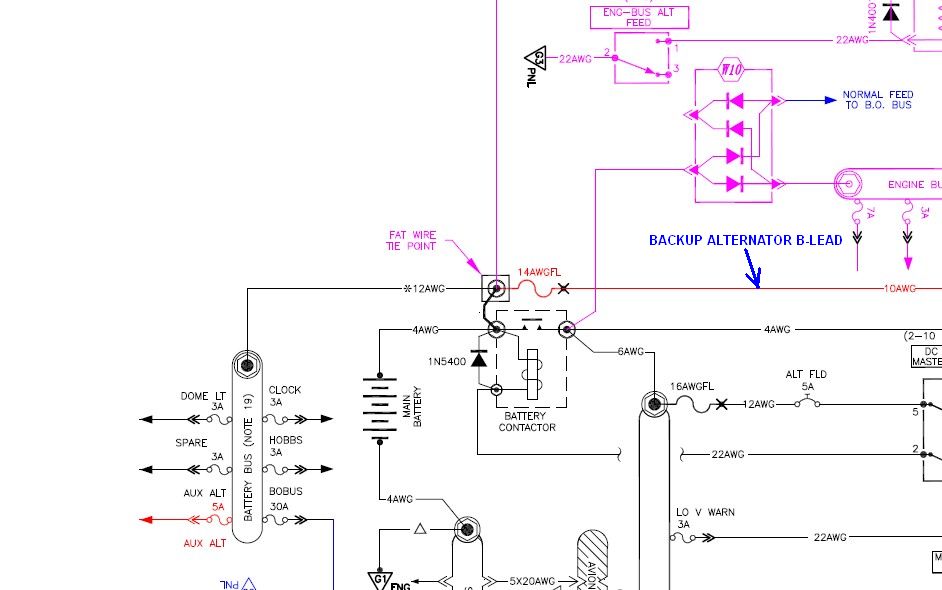
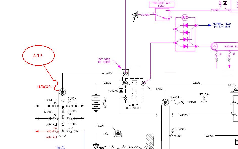
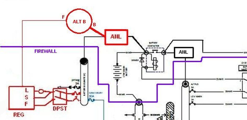
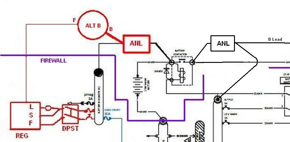
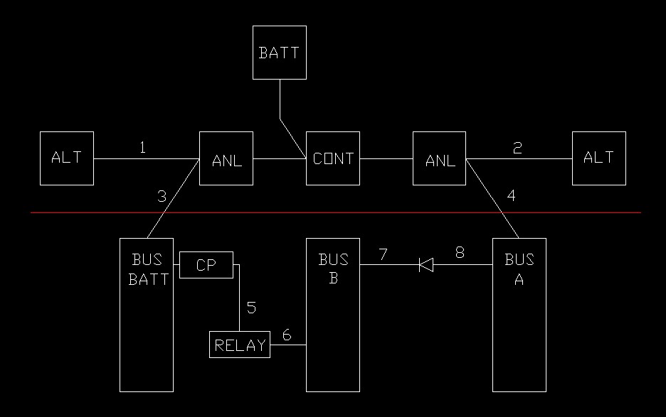
I'm following Bob's and FAR 23.1361 advice to keep power distribution wires that don't have a remote switch (relay or contactor) close to the source (battery) fused at 7.5A or less. This has implications in maintenance, smoke in the cockpit, and crash scenarios. Attaching the backup alternator B lead to the battery without a relay violates this... one can either justify this that with vacuum pad alternators the alternator is close to the battery or one can add a B lead relay adjacent the battery. Automotive service manuals say first thing, disconnect the battery minus cable.
When I say battery bus I mean the fuse block; fuse block and bus are synonyms in this case.
The B&C aux alternator controller was designed for TC aircraft and has a light that illuminates if the voltage drops due to primary alternator failure causing the aux alternator to come alive. But modern EMS systems will tell us the voltage has dropped. I found my Bob quote:
"If the bus voltage drops below the AUX controller set point, the AUX alternator wakes up and a SPECIAL
circuity within the controller senses this and illuminates an ALTERNATOR LOADED light. The stand-by versions of the alternator controller are not recommended for simple dual alternator installations where the auto-switch feature is not necessary . . . this was a 'bell-n-whistle' aimed primarily at the
STC market for TC aircraft that were receiving the pad driven, aux alternators.
... Bob"
The 5x20awg wires from the firewall ground bus to the avionics ground bus are described in Chapter 18 of Aeroelectric Connection. Note 23 in the appendix, which is called out on the dwg adjacent the avionics ground bus, points to Chapter 18. In Bobspeak the (instrument) panel ground bus is the forest of tabs on the aft side of the firewall and the avionics ground bus is on the IP subpanel.
In a smoke in the cockpit situation the progressive switch for the main bus and alternator makes sense because to de-power the main bus you need to de-power the main alternator. If the aux alternator is on the main bus and switched on I image it would come alive in time to keep itself powered but don't quote me on that but it doesn't matter because your gonna want it off because you want the main bus cold. Keep in mind Z-101 puts the aux alternator on the battery.
With Z-101 I plan to keep the aux alternator on in flight; if the main alt fails I will get an EMS message; if I open the master contactor I won't have to remember to turn the aux alternator on. If using the Ford aux regulator I'm not sure what's wrong with keeping it on but I believe there are low-cost adjustable automotive regulators. I plan on a B&C "primary" regulator set at 13.8V for the aux alternator because I'm not being as frugal as Bob and I like the OV protection.
Yes the aux alternator will come alive with Z-12 or Z-101 if it is switched on after the main alternator fails because the battery is there to energize the field; I the case of Z-12 the master contactor is still closed so the main bus sees the battery; in the case of Z-101 the the aux alternator field is connected to the battery bus so it will come alive even with the battery contactor open.
Keep in mind the AeroElectric Connection book is not updated as often as the drawings at
http://www.aeroelectric.com/PPS/Adobe_Architecture_Pdfs/
Changes I made to Z-101:
- Renamed clearance delivery bus to avionics bus and fed it from opposite ends from battery bus and main bus versus using a single post on the bus.
- Put com 1 on the engine bus with the idea if you kill both the main and avionics busses, you?ll still have a radio.
- Added electronic fuel injection and ignition components.
- Added Crowbar Test buttons to main and battery regulators for annual.
- Used B&C LR3C regulator for battery alternator versus generic Ford.
- Alternator B leads: Used MIDI current limiters versus fuselinks.
- Aux alternator switch is progressive.
- I show an optional aux bus B lead relay.
- Battery contactor is a low coil current version.
- Diodes are schottky.


 )
)