
Van's Air Force
You are using an out of date browser. It may not display this or other websites correctly.
You should upgrade or use an alternative browser.
You should upgrade or use an alternative browser.
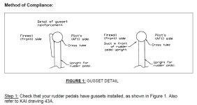
Rudder Pedal SB 99-6-1
- Thread starter Smak
- Start date


By who’s direction?
Gerard,
Have you turned in the part for an engineering assessment, perhaps to Van’s? Are you relaying Van’s engineers’ direction to suspend the SB? That failure is pretty notable, and I’m glad you two are OK, but I would caution folks against simply ignoring a standing bulletin without getting a solid engineering assessment into why that happened.
Kyle Boatright
Well Known Member
Gerard,
Have you turned in the part for an engineering assessment, perhaps to Van’s? Are you relaying Van’s engineers’ direction to suspend the SB? That failure is pretty notable, and I’m glad you two are OK, but I would caution folks against simply ignoring a standing bulletin without getting a solid engineering assessment into why that happened.
The SB is for a 10 hour inspection, with replacement if any sponginess, hard rudder forces, etc. are experienced. Here's a link:
https://www.vansaircraft.com/wp-content/uploads/2019/01/sb99-06-1.pdf
I figured 20 years down the road everyone had already modified their rudder pedals to get past the issue.
I'd recommend people make the mod/upgrade. Ain't hard, relatively speaking.
azrv6
Well Known Member
An important reminder from the original poster to all RV6 and RV6A owners, many who are new to their aircraft, to verify the status of SB 99-6-1.
Although the SB provides the option to inspect the overhead rudder pedals every 10 hours, and explains how to inspect them, it is a much better course to repair or replace them per info in the SB.
I built my RV6 and have been flying it for 25 years. I replaced my overhead rudder pedals soon after the SB was published and inspection required replacing them. Ordered from Vans and several hours later the new pedals were installed.
Last edited:
Smak
Member
An important reminder from the original poster to all RV6 and RV6A owners, many who are new to their aircraft, to verify the status of SB 99-6-1.
Although the SB provides the option to inspect the overhead rudder pedals every 10 hours, and explains how to inspect them, it is a much better course to repair or replace them per info in the SB.
I built my RV6 and have been flying it for 25 years. I replaced my overhead rudder pedals soon after the SB was published and inspection required replacing them. Ordered from Vans and several hours later the new pedals were installed.
Exactly my intention. I’m new to the RV world and my ( ew do me RV) was in full compliance with this and all SBs. I expressed as strongly as I know how to Sterling at Van’s tech support that this SB be changed, removing the inspection option and “requiring” replacement or reinforcing. The wisdom I’m getting from those who have seen the parts break is that the weld wasn’t cooled properly (by applying heat) and that weekend the torque tube, which was the point of failure.
I have new rudder pedals on the way. They of course now come with gusset reinforcement.
yes, a 10 hr inspection interval for a part like this is nonsense. it should be a strict replacement.
an end tube welded connection like this is not designed to withstand hundreds of pounds of cycling load in bending. the stress concentration at the welded joint is the limiting feature.
there is only one thing more important than the engine.... the flight controls.
an end tube welded connection like this is not designed to withstand hundreds of pounds of cycling load in bending. the stress concentration at the welded joint is the limiting feature.
there is only one thing more important than the engine.... the flight controls.
Last edited:
DennisRhodes
Well Known Member
I checked my RV9 "older kit " yesterday. Appears to have all the gusset reinforcements as mentioned. An while you're standing on you head may as well check all the other welds and cable connections . All looked "fine on the 9".
A few comments......
I was at Van's for the static testing of rudder pedal assemblies that we did after we first became aware of a weldment failure, and when this SB was issued.
An SB issued by a kit manufacturer has no regulatory basis. An owner can choose to totally ignore it if they like. The compliance time / method is often chosen by us to imply a level of urgency, but to also give some latitude for aircraft repositioning to have the work done by someone else, scheduling of that work, etc., but as already mentioned, it is some what a moot point because there is nothing regulatory about compliance with an SB on an experimental.
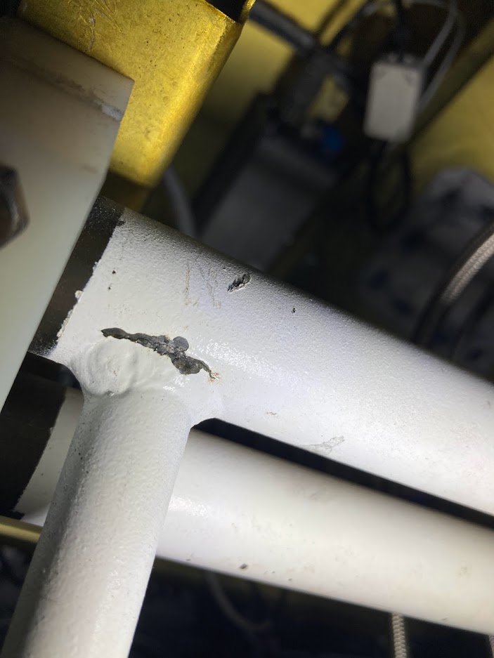
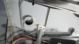
The failure noted in the attached photo is nothing like the actual original failure that the gussets prescribed by the SB were designed to prevent.
The gussets might have prevented this failure if they had been installed, because they do change the load distribution, but this failure mode is not the same.
The actual failure mode being prevented by the addition of the gussets was a buckle failure on the side of the tube loaded in compression under load from high foot pressure. That is why the gussets are added to only one side of each tube, and why some are on the fwd. side, and some are on the aft side (depending on which side of the tube is highly loaded in compression when rudder / brake pressure is applied).
The following is my opinion based on experience and a bit of logical reason thrown in for good measure....
I do not think this failure occurred within the span of 10 flight hrs (Reasons described below). An inspection may have been done, but I think evidence of already existing damage was missed.
One piece of info (if known) that would support my opinion is knowing what the total time in service is.
Since the airplane has ungusseted weldments, it is likely an older build (finish kit predating the issuance of the SB in 1999) which has probably accumulated quite a few flight hrs without a failure.
If the failure has occurred through just the past 10 hrs, there would have to be something that changed in the operation of the airplane very recently that made the assembly fail now but not long ago.
I know that the current owner recently purchased the airplane. An RV changing ownership usually results in an investigation of applicable SB's and whether they were complied with.
It is entirely possible that the original builder (and possibly prior owners, if there was more than one) didn't know about the SB and had never inspected the rudder pedal assemblies for this type of failure.
If that were the case, the crack that ultimately cause the failure could have been propagating for quite some time.
Couple of side comments to the main subject-
Painting any welded assembly a dark color (black would be the absolute worst choice) is a very bad idea. It makes cracks just about impossible to visually detect. That is why we have always used very light grey or white for the color on all of our powder coated parts.
Inspection of welded assemblies like the rudder pedals is something that should be done with a high level of scrutiny during a condition inspection. An SB like this is issued to highlight an area that has become know to potentially develop a problem, but in reality it should already have been being inspected.
Primary point there is that just because an SB has been physically complied with, doesn't mean that you don't need to inspect that area any longer.
I was at Van's for the static testing of rudder pedal assemblies that we did after we first became aware of a weldment failure, and when this SB was issued.
An SB issued by a kit manufacturer has no regulatory basis. An owner can choose to totally ignore it if they like. The compliance time / method is often chosen by us to imply a level of urgency, but to also give some latitude for aircraft repositioning to have the work done by someone else, scheduling of that work, etc., but as already mentioned, it is some what a moot point because there is nothing regulatory about compliance with an SB on an experimental.
The failure noted in the attached photo is nothing like the actual original failure that the gussets prescribed by the SB were designed to prevent.
The gussets might have prevented this failure if they had been installed, because they do change the load distribution, but this failure mode is not the same.
The actual failure mode being prevented by the addition of the gussets was a buckle failure on the side of the tube loaded in compression under load from high foot pressure. That is why the gussets are added to only one side of each tube, and why some are on the fwd. side, and some are on the aft side (depending on which side of the tube is highly loaded in compression when rudder / brake pressure is applied).
The following is my opinion based on experience and a bit of logical reason thrown in for good measure....
I do not think this failure occurred within the span of 10 flight hrs (Reasons described below). An inspection may have been done, but I think evidence of already existing damage was missed.
One piece of info (if known) that would support my opinion is knowing what the total time in service is.
Since the airplane has ungusseted weldments, it is likely an older build (finish kit predating the issuance of the SB in 1999) which has probably accumulated quite a few flight hrs without a failure.
If the failure has occurred through just the past 10 hrs, there would have to be something that changed in the operation of the airplane very recently that made the assembly fail now but not long ago.
I know that the current owner recently purchased the airplane. An RV changing ownership usually results in an investigation of applicable SB's and whether they were complied with.
It is entirely possible that the original builder (and possibly prior owners, if there was more than one) didn't know about the SB and had never inspected the rudder pedal assemblies for this type of failure.
If that were the case, the crack that ultimately cause the failure could have been propagating for quite some time.
Couple of side comments to the main subject-
Painting any welded assembly a dark color (black would be the absolute worst choice) is a very bad idea. It makes cracks just about impossible to visually detect. That is why we have always used very light grey or white for the color on all of our powder coated parts.
Inspection of welded assemblies like the rudder pedals is something that should be done with a high level of scrutiny during a condition inspection. An SB like this is issued to highlight an area that has become know to potentially develop a problem, but in reality it should already have been being inspected.
Primary point there is that just because an SB has been physically complied with, doesn't mean that you don't need to inspect that area any longer.
Scott,
What a well-stated comment. To me the biggest take-away is that the part appeared to have failed in a manner completely outside the failure mode addressed by the SB. Another reason for RV-6 drivers to NOT disregard the SB (as the OP so urgently urges).
Since this part failed at the weld, I’m curious to know whether there is a history of such failures? I can’t tell if the cross tube was internally primed, which is supposed to decrease the chance of corrosion developing at the weld.
Walt
Well Known Member
I have spotted a few of these cracks on older RV6's, they were always on the side or back and are not easy to spot unless you know what to look for.
Despite the owner thinking it was fine 10 hours ago I find that highly unlikely as cracks/failures like this are always progressive in nature (unless a gorilla was flying it perhaps).
Despite the owner thinking it was fine 10 hours ago I find that highly unlikely as cracks/failures like this are always progressive in nature (unless a gorilla was flying it perhaps).
Scott,
What a well-stated comment. To me the biggest take-away is that the part appeared to have failed in a manner completely outside the failure mode addressed by the SB. Another reason for RV-6 drivers to NOT disregard the SB (as the OP so urgently urges).
Since this part failed at the weld, I’m curious to know whether there is a history of such failures? I can’t tell if the cross tube was internally primed, which is supposed to decrease the chance of corrosion developing at the weld.
The few instances of failure that I am familiar with all had a noticeable indication of a compression buckling failure as the start of the failure sequence, which then progressed to cracking along the weld and then ultimately total failure.
In this instance, there may be signs of a buckling failure but just not evident in the one photo.
One thing that is interesting to me is what occurred at the neutral axis of the tube intersections (The point where the load is transitioning from a tension to a compressive load). See attached photo.
It was likely the last area to fail and since the crack hadn't yet propagated through that area, the failure was just pure overload on the remaining un-cracked material so it just tore the material. I think that is what caused the squarish shaped areas beyond the edge of the weld. Just prior to these areas failing the loads were probably being transferred simply by the edge of one cracked piece, pressing against the edge of the other cracked piece.
(but that is just a guess... it would take a closer look with some higher powered magnification to see if there is any actual evidence of that.
Attachments
As an owner of a "New to me" RV-6
I wonder how many failures are being experienced by new owners of legacy RV-6s. I have flown a number of airplanes that you could do jumping jacks on the rudder pedals without hurting them. And, if hadn't been aware of this SB before I bought mine, I might not have had enough appreciation for the opportunity to overload the pedal system with lead feet.
Too bad there isn't a way to have a "Tell Tale" incorporated into the system to give a heads up that an overload may have been experienced...
Too bad there isn't a way to have a "Tell Tale" incorporated into the system to give a heads up that an overload may have been experienced...
On a side by side RV equipped with pedals that have had the gussets properly installed, damage occurring from overload is unlikely, but the "tell tail" would be the discovery of it early while properly conducting a yearly condition inspection.
Scott, if possible can you say how much load was applied during the testing to achieve a failure?
As mentioned in the SB document, an un-modified assembly was found to meet the load requirements dictated by FAR 23, but that since failures had occurred, it was re-enforced anyway.
I remember that when testing a gusseted assembly, the load value at failure was substantially higher than the un-gusseted test article, but I do not remember any specific values.
Smak
Member
Scott,
What a well-stated comment. To me the biggest take-away is that the part appeared to have failed in a manner completely outside the failure mode addressed by the SB. Another reason for RV-6 drivers to NOT disregard the SB (as the OP so urgently urges).
Since this part failed at the weld, I’m curious to know whether there is a history of such failures? I can’t tell if the cross tube was internally primed, which is supposed to decrease the chance of corrosion developing at the weld.
No internal primer on the Torque Tube, but they are clean and show no sign of corrosion. Total time on the Aircraft is approximately 500 hours. First flight in 2001 so She's 20 years old...As to the guy who's post you like, my opinion is he's dead wrong on signs of cracking that were missed within 10 hours. The wisdom from local engineers who have looked at the part is that the weld was not "normalized" with heat and this weakened the Torque tube (crystalizing some of the internal metal) which was the point of failure, NOT the weld itself which is entirely intact. Powder coating a dark color is a very bad idea, and personally I wouldn't do it at all but the new ones from Van's come powder coated in white.
Smak
Last edited:
Smak
Member
Scott,
What a well-stated comment. To me the biggest take-away is that the part appeared to have failed in a manner completely outside the failure mode addressed by the SB. Another reason for RV-6 drivers to NOT disregard the SB (as the OP so urgently urges).
Since this part failed at the weld, I’m curious to know whether there is a history of such failures? I can’t tell if the cross tube was internally primed, which is supposed to decrease the chance of corrosion developing at the weld.
Tube not internally primed but no sign of corrosion either. Local engineers who have inspected the failure conclude that the weld was not "normalized" thereby leaving the torque tube with some crystallization and weakness. The weld is not the point of failure...The Tube is, subtle but significant difference.
I made a 90 right on Taxi out, felt something, let's say "weird" and thought it was just the tailwheel taking a bit to recenter. I made a Full Control Check just before takeoff and that's when the right pedal stayed full forward. I now believe the one side/arm snapped off with that first 90 right and the second broke loose with the control check. About 500 hours on a '96 kit completed in 2001.
A&P IA with the Absolute Best Paperwork I've ever seen had just signed off the SB on a pre purchase conditional inspection...LESS than 10 hours before failure.
Put the new pedals on!
Smak
Planned SB Revision
We've reviewed this as well as other past reports, and Van's Aircraft will be revising SB 99-6-1, removing the option for compliance by inspection every 10 hours. The original service bulletin was issued more than 20 years ago. Any aircraft that has not yet been brought into compliance by replacing or modifying the pedals has likely experienced a significant number of years/hours in service. Therefore, the potential is now even greater for existing unmodified parts to be weakened as a result of use and environmental factors.
Our engineering team has therefore determined that the proper course of action is to revise the SB to require either replacement of the parts with the current version, or reinforcement of the existing pedals with the gusset kit that's been available free of charge from Van's since 1999. The details are in the service bulletin document, and we plan to publish the revised version on Thursday before the close of business.
While compliance with service bulletins is technically at the discretion of the owner/operator of the aircraft, Van's Aircraft strongly recommends complying with all service bulletins, including achieving compliance by implementing the changes outlined in this bulletin for operational safety reasons.
AJ85WA
Well Known Member
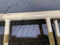
I found cracks also
I have been doing my condition inspection over the past week and i also found cracks on my pedals, parts have been ordered.
The paint on most of my rudder pedals have all chipped away at the welds which suggests to me there is some movement, but 100% cracks were spoted on the back of the pedals.
They look like this.
https://photos.app.goo.gl/PxfgTHiiePnvhAK26
Last edited:
The revised service bulletin has been published.
Smak
Member
good. issue the revision and move on.
Got the email from Sterling at Van’s today (been busy picking up an airplane) that the update is in!
I’m Satisfied!!
Also, even though compliance is not mandatory (as with a certified AD), I implore you!! Make the Repair or Swap.
https://www.vansaircraft.com/service-information-and-revisions/sb-99-06-1/
Im the OP who started this thread and swore I’d see this through!!
Smak
Jetmart
Well Known Member
Got the email from Sterling at Van’s today (been busy picking up an airplane) that the update is in!
I’m Satisfied!!
Also, even though compliance is not mandatory (as with a certified AD), I implore you!! Make the Repair or Swap.
https://www.vansaircraft.com/service-information-and-revisions/sb-99-06-1/
Im the OP who started this thread and swore I’d see this through!!
Smak
Good for you.
The wisdom from local engineers who have looked at the part is that the weld was not "normalized" with heat and this weakened the Torque tube (crystalizing some of the internal metal) which was the point of failure, NOT the weld itself which is entirely intact.
Smak
I have done a fair amount of research on this subject and the general wisdom in the welding community is that when TIG or gas welding of 4130 at thicknesses less than 1/8", normalizing is not necessary to maintain strength and integrity. precautions do exist to ensure that pre-heating is conducted when surface temps are below 70*. Pre heating the weld to 200* is good insurance when welding 4130.
Cracks will almost universally appear in the HAZ (where the crystal structure changes) on a weld like this, as it is the weak point, but that doesn't mean it did not meet the designed strength of the welded joint. Engineers generally discount some strength at many weld joints.
Larry
Last edited:
PaulvS
Well Known Member
Welding
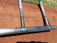
My rudder pedals have beein reinforced with the finger patches supplied by Vans, I just picked them up from the welder today. The pedals have not been previously installed, since I'm still building.
It took just over 2 hours of labour to fix the pedals and also to put the gussets on the steps (to prevent them from cracking.) The 8 finger patches as supplied by Vans were not a good fit to the rudder tube and needed a bit of grinding. The welder normalized the welds after using TIG.
Pic attached and I am very happy with the way they turned out and hope they will do their job for the life of the plane.
Attachments
LouFly
Well Known Member
Compression Cracks
I'm not a welding expert but am a mechanical engineer. It's clear that it's unrelated to any welding technique heat treatment. The pedal is simply being forced into the tube.
Back from the bead blast, the compression crack is invisible from front or back but very obvious from the bottom. So to really see it you'd have to luck vertically from the floor underneath the pedal.
So, my pedals are off to Russ McCutcheon to make them right.
Untainted123
Well Known Member
Mandatory Means Mandatory
My scenario was almost the same: I taxied, and on take off and right rudder application, things felt a little less than authoritative, and I attributed it to a crosswind. Flew to a nearby airport to pick up a friend and do some night flying and landed, but the steering seemed a little squirrelly, still not really thinking anything is wrong, just the normal tail-wheel games (all right turns at this airport to the ramp). Friend jumped in, we called ground for taxi, and as we started taxiing, my right pedal gave way completely, I gave him the controls and he taxied us back. I pried the pedal forward, and it came off completely.
This is a new-to-me RV-6, 1997, ~1150hr. When this thread first started, I went and "inspected" my rudder pedals, but I couldn't find any chipped paint or any apparent cracks (probably didn't realize well enough what to look for). I kept telling myself, I need to get that rudder pedal SB done, it could be serious if that actually fails...
I have ordered the gussets tonight from Van's, but now I wonder: are my current pedals repairable once they are broken? Or do I need all new assemblies? I didn't get a very good picture, but here it is:

Either way, it appears everything is backordered, so I am on the ground until I get something.
Meanwhile, another friend saw me getting ready to takeoff, and snapped a pic before the "interesting" flight. As DR mentions on the homepage, beautiful evening/night for flying, but things work out like they do for a reason...

I made a 90 right on Taxi out, felt something, let's say "weird" and thought it was just the tailwheel taking a bit to recenter. I made a Full Control Check just before takeoff and that's when the right pedal stayed full forward. I now believe the one side/arm snapped off with that first 90 right and the second broke loose with the control check. About 500 hours on a '96 kit completed in 2001.
...
Put the new pedals on!
Smak
My scenario was almost the same: I taxied, and on take off and right rudder application, things felt a little less than authoritative, and I attributed it to a crosswind. Flew to a nearby airport to pick up a friend and do some night flying and landed, but the steering seemed a little squirrelly, still not really thinking anything is wrong, just the normal tail-wheel games (all right turns at this airport to the ramp). Friend jumped in, we called ground for taxi, and as we started taxiing, my right pedal gave way completely, I gave him the controls and he taxied us back. I pried the pedal forward, and it came off completely.
This is a new-to-me RV-6, 1997, ~1150hr. When this thread first started, I went and "inspected" my rudder pedals, but I couldn't find any chipped paint or any apparent cracks (probably didn't realize well enough what to look for). I kept telling myself, I need to get that rudder pedal SB done, it could be serious if that actually fails...
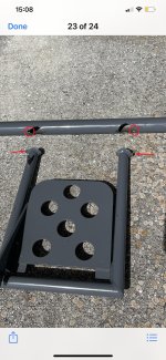
I have ordered the gussets tonight from Van's, but now I wonder: are my current pedals repairable once they are broken? Or do I need all new assemblies? I didn't get a very good picture, but here it is:
Either way, it appears everything is backordered, so I am on the ground until I get something.
Meanwhile, another friend saw me getting ready to takeoff, and snapped a pic before the "interesting" flight. As DR mentions on the homepage, beautiful evening/night for flying, but things work out like they do for a reason...
The actual failure mode being prevented by the addition of the gussets was a buckle failure on the side of the tube loaded in compression under load from high foot pressure. That is why the gussets are added to only one side of each tube, and why some are on the fwd. side, and some are on the aft side (depending on which side of the tube is highly loaded in compression when rudder / brake pressure is applied).
The instructions I got with my gussets don't talk about installing some on the aft side of the pedals. Seems that all the pedals would be loaded in compression on the forward (firewall) side. Can you clarify how some of the pedals could be in compression on the aft side and which ones need the gussets installed on that side, please?
PaulvS
Well Known Member
The instructions I got with my gussets don't talk about installing some on the aft side of the pedals. Seems that all the pedals would be loaded in compression on the forward (firewall) side. Can you clarify how some of the pedals could be in compression on the aft side and which ones need the gussets installed on that side, please?
The outer pedals are loaded in compression at the aft side when the inner pedal on the opposite side is pushed. For example, when the pilot pushes the right pedal (and its forward side is in compression) the torque is transferred via the long tube to the right pedal on the co-pilot side, where the rudder cable is attached. The "pull" from the rudder cable puts a compression force on the pedal aft side.
The instructions that came with the gussets that I got specified installation on the forward side only, so that's what has been done. I expect (and hope) the gussets will strengthen the joint whichever side they are welded. I vaguely recall (so may be wrong!) that there might also be some conflict with installing the finger patches on the same side as the tabs for the brake cylinders.
Last edited:
The outer pedals are loaded in compression at the aft side when the inner pedal on the opposite side is pushed. For example, when the pilot pushes the right pedal (and its forward side is in compression) the torque is transferred via the long tube to the right pedal on the co-pilot side, where the rudder cable is attached. The "pull" from the rudder cable puts a compression force on the pedal aft side.
The instructions that came with the gussets that I got specified installation on the forward side only, so that's what has been done. I expect (and hope) the gussets will strengthen the joint whichever side they are welded. I vaguely recall (so may be wrong!) that there might also be some conflict with installing the finger patches on the same side as the tabs for the brake cylinders.
Ah. Thanks. Now that makes sense. There is no load on the pedal that the cable is attached to when it is being pressed by the pilot, but when the force is transferred by the tube from the other side the compressive force is felt on the aft side of that pedal. Van's needs to update its instructions to reflect that.
charosenz
Well Known Member
charosenz
Well Known Member
removing rudder pedal assembly tip with pic
Since it was time for my Condition Inspection, I bit the bullet to remove the pedal assembly for the Service Bulletin repair.
Between my vents being a bit low and my fuel tank vent line, I could NOT get them out.... I complained outloud and my wife who was helping, said "let me do it"! I manned up and said..... "Go for it".
Well you know of course what happened. Get got them out. I was torn between being super happy and somewhat embarrassed.
The trick she showed me was the importance of getting one of the ends with the nylon block to slip/nudge BELOW the horizontal angle that they sit on. This then allows you (or your wife) to get enough angle on the assembly to swing one end pass the vertical angle so they can come out.
THEN I will definitely split those end blocks like the middle one before I even try to get it back in.
Thanks to the others who have posted here. Several tips others posted were very helpful.
p.S. My weld joints were 100% rock solid. I think they were purchased over 10 years ago but I just got the kit flying a year ago so they only had about 140 hours on them.
Charlie
Attachments
Untainted123
Well Known Member
p.S. My weld joints were 100% rock solid. I think they were purchased over 10 years ago but I just got the kit flying a year ago so they only had about 140 hours on them.
Charlie
If they don't have the gussets, I still wouldn't trust them. Mine went from "rock solid" to totally broken off in a short time.
While you have everything apart, it's worth it to do some of the brake mods listed on here too. The one that made a big difference for me and the "freeness" of my brake pedals was the long bolt mod. Followed by better/stiffer springs (or more spacers to make them return "harder"). After that, my brakes no longer felt draggy.

