

Bubblehead
Well Known Member
When I installed my GRT EIS-4000 I struggled to find an elegant solution to wiring resistors between the 4.8 v power from the EIS to the Aux signal lines. I thought I could make something using a terminal strip and fast-on tabs that would allow troubleshooting and reliable operation and future modifications to add or change aux components.
Here is a picture of what I came up with.
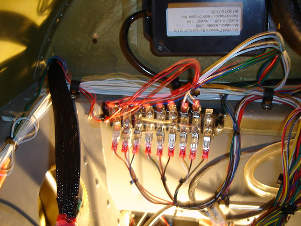
It met the requirements stated above, but looks a little sloppy.
I have been using the EIS now for 100 hours of operation and for fun I've been letting my brain work on better solutions. I think I have one but need some help with someone who can make a circuit board for me. The concept is to use a small pc board with either board mounted DB-9 connectors or Fast-on tabs mounted on it. The board would have holes and pads for insertion and soldering the correct resistors in place for each aux channel.
Here is a schematic I made with "ExpressSCH." Picture this with the EIS wires connected on the left and wires to the sensors (amps, fuel pressure etc.) on the right.
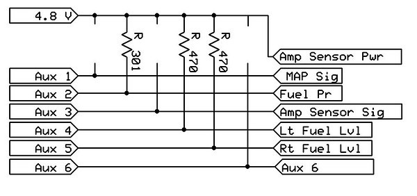
If the circuit board could be made small enough perhaps the wire connections could be made through soldered connectors and the whole assembly covered with a heat-shrink covering. Or the board could be mounted in a small project box and mounted on the airframe.
Is there anyone out there that dabbles in this sort of project that could help me try some things out? If so contact me at my email address and we'll set a time to discuss by phone. [email protected]
Thanks,
John
Here is a picture of what I came up with.
It met the requirements stated above, but looks a little sloppy.
I have been using the EIS now for 100 hours of operation and for fun I've been letting my brain work on better solutions. I think I have one but need some help with someone who can make a circuit board for me. The concept is to use a small pc board with either board mounted DB-9 connectors or Fast-on tabs mounted on it. The board would have holes and pads for insertion and soldering the correct resistors in place for each aux channel.
Here is a schematic I made with "ExpressSCH." Picture this with the EIS wires connected on the left and wires to the sensors (amps, fuel pressure etc.) on the right.
If the circuit board could be made small enough perhaps the wire connections could be made through soldered connectors and the whole assembly covered with a heat-shrink covering. Or the board could be mounted in a small project box and mounted on the airframe.
Is there anyone out there that dabbles in this sort of project that could help me try some things out? If so contact me at my email address and we'll set a time to discuss by phone. [email protected]
Thanks,
John

