

Could we use a modified ELT antenna for an APRS antenna? An ELT antenna would be around 22", could it be trimmed down to 19"?
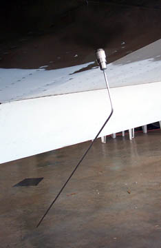
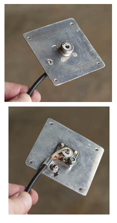
This is the type of antenna I have for my ELT that would look nice to install on the bottom of the plane for APRS purposes. It's pricey at $69. Aircraft Spruce has one for $45 that might work (11-17961). I don't know the internal construction of these to know if they could be "cut".

This is the type of antenna I have for my ELT that would look nice to install on the bottom of the plane for APRS purposes. It's pricey at $69. Aircraft Spruce has one for $45 that might work (11-17961). I don't know the internal construction of these to know if they could be "cut".


")

