zkvii
Well Known Member
Hi,
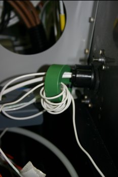
Specifically GRT supplied AMPLOC100 (green donuts). We have two and have been getting them installed and setup over the past days. The calibrartion numbers that we have recieved however seem to be rather off.
First question - if you have HE sensors - have you checked / calibrarted your setup - yes / no - results?
My test methodology: Take known current drain (land light = 6.4AMP) and run the cable X times through the donut. Use a sensitive fluke to measure the 'green wire' output voltage from the HE whilst using the EIS4000 for the Blue 4.8/5V reference and ship / common ground. The multiple pass through of the wires is just to be able to 'generate' an 80+ Amp load with a 6.4 Amp landing light.
Question - is this fundemental assumption about workings / testing of a HE valid?
The following Amp values are using the standard ScaleFactor=186 and ScaleOffset=-179 (EIS entered value as 357).
For background: Value=((Voltage*ScaleFactor)/2.5 ) + ScaleOffset
This is just so far out of whack that is it 'informational' at best, misleading at worst.
Question: Is this inaccuracy normal?
Question: Is this variation between 'identical' HE sensors normal?
I was under the understanding that HE should be an accurate measurement device (Maxwell's laws and all that). So after spending most of a day investigating and working various options, I found the B HE was pretty linear in sensing and using SF=1602 and SO=3057 (did you know EIS factors went THAT high?) with decimal values I get resulting values which are within .5 amp of measured (StdDeviation of .12) - really good and impressed with.
However with the A sensor tailing off at 60ish amps, it is impossible to get a decent calibration line for the whole range, so a rethink is needed there anyway.
So final questions: Are we on our own here, just one / a dodgy pair of sensors? Are we expecting too much? What checks / calibrartion have others done?
Thanks,
Carl
Specifically GRT supplied AMPLOC100 (green donuts). We have two and have been getting them installed and setup over the past days. The calibrartion numbers that we have recieved however seem to be rather off.
First question - if you have HE sensors - have you checked / calibrarted your setup - yes / no - results?
My test methodology: Take known current drain (land light = 6.4AMP) and run the cable X times through the donut. Use a sensitive fluke to measure the 'green wire' output voltage from the HE whilst using the EIS4000 for the Blue 4.8/5V reference and ship / common ground. The multiple pass through of the wires is just to be able to 'generate' an 80+ Amp load with a 6.4 Amp landing light.
Question - is this fundemental assumption about workings / testing of a HE valid?
The following Amp values are using the standard ScaleFactor=186 and ScaleOffset=-179 (EIS entered value as 357).
For background: Value=((Voltage*ScaleFactor)/2.5 ) + ScaleOffset
Code:
Results:
Passes	AMP 	AVolt	BVolt	AAmp	BAmp
0	0	2.385	2.39	-1	0
1	6.4	2.618	2.491	17	7
2	12.8	2.854	2.591	34	15
3	19.2	3.084	2.691	51	22
4	25.6	3.316	2.791	69	30
5	32	3.55	2.893	86	37
6	38.4	3.8	2.992	105	45
7	44.8	4.02	3.094	121	52
8	51.2	4.23	3.189	137	59
9	57.6	4.49	3.289	156	67
10	64	4.72	3.388	173	74
11	70.4	4.74	3.486	175	81
12	76.8	4.74	3.59	175	89
13	83.2	4.74	3.69	175	97
This is just so far out of whack that is it 'informational' at best, misleading at worst.
Question: Is this inaccuracy normal?
Question: Is this variation between 'identical' HE sensors normal?
I was under the understanding that HE should be an accurate measurement device (Maxwell's laws and all that). So after spending most of a day investigating and working various options, I found the B HE was pretty linear in sensing and using SF=1602 and SO=3057 (did you know EIS factors went THAT high?) with decimal values I get resulting values which are within .5 amp of measured (StdDeviation of .12) - really good and impressed with.
Code:
AMP	BAmp
0	0.4
6.4	6.8
12.8	13.2
19.2	19.6
25.6	26.0
32	32.6
38.4	38.9
44.8	45.5
51.2	51.6
57.6	58.0
64	64.3
70.4	70.6
76.8	77.2
83.2	83.7
However with the A sensor tailing off at 60ish amps, it is impossible to get a decent calibration line for the whole range, so a rethink is needed there anyway.
So final questions: Are we on our own here, just one / a dodgy pair of sensors? Are we expecting too much? What checks / calibrartion have others done?
Thanks,
Carl