Fenderbean
Well Known Member
I was wondering about the forward vertical stab mount bracket. After seeing the design and the single aluminum bracket with a bolt, is it safe to assume the main rear spar is most of the strength?

I will follow Vans manual like always; thanks figured such a simple bracket couldn't be structural in the sense of main load.Yes.
Remember that single bolt has a castle nut with cotter pin. Don’t let the DAR find you used a nyloc nut instead.
Carl
Structural loads can be transferred through fixed, pinned, or sliding connections. This joint is intentionally designed as a pinned connection, allowing rotation about the bolt while transferring the required shear loads without developing significant bending moments. The flap piano hinge operates on the same principle, although it permits a much larger range of rotation about the hinge pin. If either joint were made rigid, normal control surface movement and structural deflection would generate high cyclic bending stresses. Over thousands of flight cycles, those stresses could initiate fatigue cracks and eventually lead to structural failure.I will follow Vans manual like always; thanks figured such a simple bracket couldn't be structural in the sense of main load.
...and don't forget the NeverSeize on the bracket face.I will follow Vans manual like always; thanks figured such a simple bracket couldn't be structural in the sense of main load.
Are we talking about the same thing? Im referring to the forward vertical stab attachment to the horizontal stab.Structural loads can be transferred through fixed, pinned, or sliding connections. This joint is intentionally designed as a pinned connection, allowing rotation about the bolt while transferring the required shear loads without developing significant bending moments. The flap piano hinge operates on the same principle, although it permits a much larger range of rotation about the hinge pin. If either joint were made rigid, normal control surface movement and structural deflection would generate high cyclic bending stresses. Over thousands of flight cycles, those stresses could initiate fatigue cracks and eventually lead to structural failure.
Thanks, I need to get something for this and all bolt installations. Are you referring to "Never- seez" or something else?...and don't forget the NeverSeize on the bracket face.
Yes, corrected: Never-Seez. Agree with DW; other than maybe spark plug threads, you won't use it much on this kit.Thanks, I need to get something for this and all bolt installations. Are you referring to "Never- seez" or something else?
Currently building the tail cone elevators
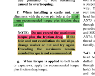
This is what the 10 and 14 plans call for (I am assuming you are discussing this bolt) calling out Anti-Seize in the 10 and 14 plans. The 14 plans do a little bit better job of documenting this but unfortunately the well specified meaning of (bolt the using hardware called out in Figure 1 is a little unknown). I've seen builders torque to a cotter position and then back off to insert the pin, and I've seen builders once more torque to the correct value and then go to the next cotter position possible. The "loose is better camp (to allow the bracket to pivot) has created in some cases the hole to "woller out" yes not very technical I know but that's what occurs. Mine are tight (14 and 10) and don't allow the bracket to free float but maybe some movement occurs with the anti-seize in place? Aeronautical engineers welcome to correct what is the proper torque procedure is.I was wondering about the forward vertical stab mount bracket. After seeing the design and the single aluminum bracket with a bolt, is it safe to assume the main rear spar is most of the strength?


Proper procedure for castle nuts is to torque to the minimum recommend torque (plus drag) and then go tighter if required to get to a cotter pin slot.This is what the 10 and 14 plans call for (I am assuming you are discussing this bolt) calling out Anti-Seize in the 10 and 14 plans. The 14 plans do a little bit better job of documenting this but unfortunately the well specified meaning of (bolt the using hardware called out in Figure 1 is a little unknown). I've seen builders torque to a cotter position and then back off to insert the pin, and I've seen builders once more torque to the correct value and then go to the next cotter position possible. The "loose is better camp (to allow the bracket to pivot) has created in some cases the hole to "woller out" yes not very technical I know but that's what occurs. Mine are tight (14 and 10) and don't allow the bracket to free float but maybe some movement occurs with the anti-seize in place? Aeronautical engineers welcome to correct what is the proper torque procedure is.
View attachment 121450View attachment 121452
Since this document is over 700 pages can you give us less gifted readers section number? (Hopefully cover brackets with Anti-Seize bolted) ThanksProper procedure for castle nuts is to torque to the minimum recommend torque (plus drag) and then go tighter if required to get to a cotter pin slot.
AC43.13 refers
Completely aware of torque requirements and the AC43. Military follows the same torquing procedures, we typically use solid film which dried like spray paint on all exposed threads. Never seen once affect torque but again like always I follow the manual from vans and the required torque for the bolt and nuts used. CheersProper procedure for castle nuts is to torque to the minimum recommend torque (plus drag) and then go tighter if required to get to a cotter pin slot.
AC43.13 refers
Yes, but you are not using spray painted solid paint. What does Vans recommend with Anti-Seize on the brackets? What does AC43.13 recommend with Anti-Seize? What does your original question assume from Vans engineering "is it safe to assume the main rear spar is most of the strength?" So, you are assuming this pivot point provides limited strength, don' think so and probably not ? Seems a rear mounted attachment point providing the majority of the structural strength might not be a great plan.Completely aware of torque requirements and the AC43. Military follows the same torquing procedures, we typically use solid film which dried like spray paint on all exposed threads. Never seen once affect torque but again like always I follow the manual from vans and the required torque for the bolt and nuts used. Cheers

AC 43.13-1B Page 7-7Since this document is over 700 pages can you give us less gifted readers section number? (Hopefully cover brackets with Anti-Seize bolted) Thanks
Doesn't clamping a bracket with Anti Seize on both surfaces change the dynamics of the system and thus the clamping torque required? I guess the question is why does Vans specify Anti-Seize on the brackets? Do they want both surfaces to move or not? This is not the design Anti-Seize documents in their torque specification guide I'm pretty sure but I'm here to learn. Per plans 10 and 14.AC 43.13-1B Page 7-7
See insert
From the Anti-Seize folks -
 ).
). I think people are just over thinking the original question. I was just wondering, seems like this bracket stabilizes the forward side of the vertical. Keeping it from moving left and right and the anti-seize is between the two plates not the bolt or threads. Again I assume this is for flexing of the vertical under normal flight causing the two plates to rub a little.Yes, but you are not using spray painted solid paint. What does Vans recommend with Anti-Seize on the brackets? What does AC43.13 recommend with Anti-Seize? What does your original question assume from Vans engineering "is it safe to assume the main rear spar is most of the strength?" So, you are assuming this pivot point provides limited strength, don' think so and probably not ? Seems a rear mounted attachment point providing the majority of the structural strength might not be a great plan.
Paul, I would acquiesce and buy all of that for a dollar if a bushing were used to deal with the rotating component, but to bear an aluminum hole on a steel bolt, and torqued castellated nut and throw in anti-seize as a means of stopping the fretting…well, you already know that the hole will enlarge over time WHEN it moves, doesn’t take much…and as soon as it starts…it continues.ALthough I have never built an RV that has the forward VS spar bolt configuration in its design, for those who think it is unusual, think about your wing attachment. One spar is firmly bolted with a bunch of fasteners. The other spar has a single bolt through a hole with a castle nut to allow some rotation/flexing. For the wing, the firmly fastened spar is the front - the rear is allowed to move a little. For the -10’s VS, it is reversed, but the idea is the same. If you have a large surface, and it is doing some twisting, the joint that is allowed some motion relieves the stress. If it was firmly bolted or riveted, there is a lot of stress at those smaller fasteners, and cracking can begin.
Why the difference between the smaller, short-wing RV’s and the -10? The size of the VS maybe? I haven’t done the math or talked to the engineers about this particular solution….but I can hypothesize. That allows me to ask better questions, which is the art of engineering…. I’ll have to ask Rian some day!
OK - so what do you think of the wing aft spar attachment on pretty much all of the low-wing RV’s? Have you changed that on yours? Do they need a bushing as well? Its the same basic concept.Paul, I would acquiesce and buy all of that for a dollar if a bushing were used to deal with the rotating component, but to bear an aluminum hole on a steel bolt, and torqued castellated nut and throw in anti-seize as a means of stopping the fretting…well, you already know that the hole will enlarge over time WHEN it moves, doesn’t take much…and as soon as it starts…it continues.
To me, it’s just a bad practice. And with ten thousand successful examples demonstrating it isn’t an issue the “old way”…zero failures…I’ve always had a tough time calling this progress. But I say the same thing about a bush plane full of pop rivets…
I’ll go back to repairing my fabric on my Waco and quit raining on the parade.
i also don't understand why if the joint is suppopsed to move, why are we tightening the bolt which would seem to be a pivot point. also agree that rotational movement around that bolt will wear away the hole ID on the plates, but have to wonder if that is really happening.Paul, I would acquiesce and buy all of that for a dollar if a bushing were used to deal with the rotating component, but to bear an aluminum hole on a steel bolt, and torqued castellated nut and throw in anti-seize as a means of stopping the fretting…well, you already know that the hole will enlarge over time WHEN it moves, doesn’t take much…and as soon as it starts…it continues.
To me, it’s just a bad practice. And with ten thousand successful examples demonstrating it isn’t an issue the “old way”…zero failures…I’ve always had a tough time calling this progress. But I say the same thing about a bush plane full of pop rivets…
I’ll go back to repairing my fabric on my Waco and quit raining on the parade.
i always assumed one bolt was due to the limited space / inability to get a second one in there vs an actual pivot point. the front spar is fully secure, yet still allows the wing to move and flex. why does the rear spar need to pivot, yet the front doesn't?OK - so what do you think of the wing aft spar attachment on pretty much all of the low-wing RV’s? Have you done that on yours? Do they need a bushing as well? Its the same basic concept.
As I have said, I am not privy to the actual engineering on the joint in question - but it is that way for a reason because they changed from what had traditionally been used.
What I feel about the aft spar joint is two-fold…OK - so what do you think of the wing aft spar attachment on pretty much all of the low-wing RV’s? Have you changed that on yours? Do they need a bushing as well? Its the same basic concept.
As I have said, I am not privy to the actual engineering on the joint in question - but it is that way for a reason because they changed from what had traditionally been used. I wouldn’t decide to change a critical attachment point until I understood the design criteria.
Don’t lose sight of the principle of arm distance vs relative movement….
The bolt is the center of rotation (if movement occurs).
The contact area on the spar extends out beyond the center of rotation point.
If there is a consequential but extremely minimal amount of movement out on the fringe edges of the spar to bracket contact area, the actual movement around the perimeter of the bolt hole would be infinitesimal.
In turn, wear within the hole would be as well.
In cases were there has been, I believe there were other factors involved.